2017-11-30
 231
231
Cat’s Laser Toy
“Pain & Gain” team
 |
Saint Petersburg, 2017
Content
Project team 3
Objective and goal 4
Operating principle (lyrics) 5
Operating principles (simulink) 6
Product design 7
Timeline 8
Budget 9
References 10
Project team

| 
| 
|
| Gintsyak Alexey | Pridanova Ekaterina | Shapovalov Roman |
| role_name_1 | role_name_2 | role_name_3 |
| alexey_ginc@mail.ru | ekaterinapridanova@gmail.com | r.g.shapovalov@mail.ru |
| 007 911 157 74 26 | 007 981 683 93 99 | 007 981 817 25 84 |

| 
| 
|
| Lisovodskaya Ksenia | Tsolan Dmitry | Shklyarova Darya |
| role_name_4 | role_name_5 | role_name_6 |
| missis.freedom@gmail.com | dimatsolan@mail.ru | elka1369@mail.ru |
| 007 953 352 43 83 | 007 911 266 28 91 | 007 999 214 97 81 |
Problem and goal
About 40% percent of people in the world have regular problems with sleep [1]. And it’s only regular ones. It’s harmful to the human’s health and has a total influence on the worker’s activity. There are a lot of reasons why a person can’t sleep well enough. One of these reasons can be the extra-loud nighttime activity of their pets.
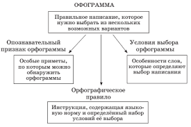
Below you can see the part of casual diagram of non-sleeping people problems (pic. 1).

Pic. 1. The casual diagram of non-sleeping people problems
Of course, we can’t solve all the problems and propose the panacea. But we try to fix one of them - to entertain the pet when it’s at home alone.
So, our goal is to create the device which helps anyone to entertain his pet without any efforts. The embodiment is the system which plays with pet with the help of laser without owner’s intervention.
Operating principle (lyrics)
First task of our system is to find a pet in the room. We decide to use something like triangulation to make this issue. We need to attach the transmitter on the pet’s collar. Thus, we assume:
1) the pet is the material point;
2) the pet is located in the same place with it’s collar.
Then, we place two sensors along the wall. They measure the distance to the transmitter (= to the pet) and then transfer these values further.
Our proposing system has one difference with the classical triangulation systems: we use only two sensors instead of three. As we know, two circles have two intersection points. In common situation it’s not enough to identify the object location. But we can use one of intersection points characteristics: they are symmetric about the straight line between centers. As we place two sensors along the wall, we guarantee that one of these intersection points is out of room, so we can define that the pet is in the other point. You can see our “triangulation” math model below (pic. 2).

Pic. 2. Pet triangulation
We have two output signals from this sensors - “a” and “b”, what means distance from our pet to sensors. Now we should evaluate the Decart coordinates of the pet. Let the origin be in the center between two sensors on the wall. The X-axis is along the wall with sensors. The Y-axis is perpendicularly to it directly to the room (pic. 3).

Pic. 3. Decart coordinates in the room
Let OA=OB=L. The systems of equations links output sensor signals and Decart coordinates of the pet:

where “L” - system parameter, “a” and “b” - independent variables, “x” and “y” - dependent variables. These evaluations are occurring inside the Arduino controller.
We have no aim to rotate the laser directly on the pet. The laser target is the point next to it (on the distance “d”, let it be 20 cm) on the pet’s route. That’s why we should define the direction of pet’s speed. We can get two components of the speed by differentiating pet’s coordinates. So below you can see the formulas of defining the coordinates of target for laser.

Laser is turning by two rotatory drivers placed on the height “h”. Each of them moves the laser point along its own axis. They are equipped by two angle sensors. These sensors measure actual angles (alpha and beta) of driver’s rotating. We propose the next method to define the laser point actual coordinates (pic. 4 and pic. 5).

Pic. 4. Defining of Y-coordinate of the laser point

Pic. 5. Defining of X-coordinate of the laser point

Then we find the difference between target position and actual position of the laser point:

These deltas are inputs for the PID-controller. It aims to make them equal to zero.
Thus, we guarantee that our system will make the laser point run away from the pet.
Operating principle (simulink)
In order to understand how our system will work we built a computer model in Simulink (pic. 6 and pic.7).

Pic.6. First part of system of cat’s laser toy in Simulink

Pic. 7. Second part of system of cat’s laser toy in Simulink
We set the following initial conditions:
● The cat is at the point with coordinates (0; 100);
● The laser is directed to the point (0; 0);
● The behavior of the cat was defined as two input noise parameters along the X-axis and Y-axis (pic. 8,9,10);


Pic.8,9. Description of cat’s noize on X and Y-axes
● Initial values of angles alpha and beta =0 degrees;
● Distance from sensors to laser - 1 meter;
● Distance from floor to laser - 1,5 meter;
● Distance from cat to target laser’s point - 0,2 meter.

Pic. 9. Cat’s behavior without system
Pet’s movement trajectory changed (pic.11) after implementation our system.

Pic.9. Cat’s behavior with system
It is worth noting that we used control loops for getting feedback about difference between target and laser coordinates on X and Y-axes (2 PID-controllers) with proportional and integral components.
Product design
The proposed model consists of details which were separates in two groups:
1. Elements for determining the position of the cat like ultrasonic rangefinder, sensor on cat’s collar
2. Elements of laser system which include laser, bracket, 2 drives for horizontal and vertical laser rotation, cables, arduino microcontroller and other details (pic. 12, 13);


Pic 12, 13. Design of product from SolidWorks
Below you can see detailed description of laser system (pic.14, 15, 16, 17, 18).

Pic 14. Bracket

Pic 15. Control block

Pic 16. Drive №1

Pic 17. Drive №2

Pic 18. Laser device
Timeline
The baseline project plan and Gantt’s diagram are represented below (pic 19, 20).

Pic.19. Project plan (1)

Pic. 20. Project plan (2)
Budget
The cost of purchasing is shown in the pic. 21.

Pic. 21. List of components
100 Euro is 6751, 67 rubles (exchange rate from 25.10.2017). Our costs keep limit.
References
1. https://www.cdc.gov/features/dssleep/index.html - Internet source: Insufficient Sleep Is a Public Health Problem - Center for Disease Control and Prevention official website;
2. we tried:(