2015-08-13
 321
3211. To acquaint itself with the experimental plant and write out nominal data of the explored motor. To measure the resistance of stator winding phase, using the chart (fig. 4.3). The current value in the stator winding is set by the R rheostat, which must not exceed the rated value.
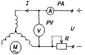 Measuring of current and voltage needs to be done not earlier, than through 15 min. after the motor switching, and to define phases resistance by the formula R 1= U/ 2 І, where U − voltmeter indication, І − ammeter indication.
To bring the measuring and calculations results in tabl. 4.1. As phase resistance take arithmetic mean of three - five measuring.
2. To assemble a circuit (fig. 4.4) and research open circuit mode, changing motor stator voltage by means Fig. 4.3 of choke within the limits of 0,6....1,0 U nom. Measuring (at this s.c. current /0 ) power of one phase Δ P 01 and phase voltage U, toread three - five indications of meters. For this purpose it is necessary to find power consumed by motor at open circuit, for every voltage value:
Δ P 0 = 3Δ P 01
________________________________________________Table 4.1
_________Measurings_________________Calculations_____
U, v 1 І, A R1, Ω Rav, Ω ______________________________________________________ ___
With the aim of parameters determination of magnetizing contour of equivalent circuit to make distribution on the mechanical losses Δ P mech and core losses Δ P c.
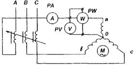
Fig. 4.4
To bring the measuring and calculations results in tabl. 4.2.
Table 4.2
Measuring______________Calculation
U, І0 ΔP 01 ΔP 0 ΔPMH ΔPc Zm Rm Xm cosφ0
v A W W W W W Ω Ω
__________________________________________________________
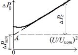
The assumption that lies in the basis of losses distribution is that the mechanical losses do not depend on stator voltage, while the core losses depend on square of voltage.
Thus

Putting aside on the abscissas axis (fig. 4.5) voltage square in the relative units, we get linear function of losses:

The mechanical losses are determined by the OA segment, that is cut off by this straight line on y-axis.
For the determination of active resistance of magnetizing contour, it is needed to divide power of core losses, found from the graph (fig. 4.5), by th proper value of s.c. current:

Impedance of magnetizing contour
Zm = U / I 0
Inductive resistance of magnetizing contour
Xm = √ (Z 2 m – R2m)
Power-factor at short circuit
Fig. 4.5 cos φ0 = Δ P 0 / 3 I 0 U
3. To define the parameters of short circuit of asynchronous motor. The determination of parameters of short circuit is carried out by circuit (see fig. 4.4), but at the blocked rotor. The stator is powered by lowered voltage, which changes by choke from zero up to the value, at which the stator current does not exceed rated value.
At short circuit experience the same electric quantities are measured, that and at open circuit experience.
Because power is measured (see fig. 4.4) in one phase only, the triple value of wattmeter indication sets to the full power.
To bring the measuring and calculations results in tabl. 4.3.
______________________________________________Table 4.3
Measuring Calculation
Usc Іsc ΔPsc Zsc Rsc Xsc cosφsc
v ______ _А W Ω Ω Ω___________
At short circuit experience the voltage brought to the motoris very lowered, therefore it is possible to neglect by the o.c. current and consider, that power brought to the motore defrays the losses in the copper of stator and rotor winding.
Active resistance of short circuit

where Δ P sc - active power of one phase, measured at short circuit experience; I sc - current of phase at the experimental short circuit.
Impedance of short circuit

where Usc - phase voltage at the motor terminals at short circuit experience.
The impedance of short circuit in machines with the closed rotor slots depends on the value of short circuit current and only at the large values of current, when core of rotor tooth is saturated, it is possible to be considered constant.
Power-factor at the short circuit

Inductive resistance of short circuit is determined similarly to short circuit experience: 
Definite from the short and open circuit experiments, the parameters of equivalent circuit of asynchronous motor allow to find the critical sliding ssc and the maximal moment Mmax by formulas (4.5) and (4.6).
The knowledge of these quantity allows by the Kloss formula:
 ; Scr = R’2 / (X 1 + X’2); Mmax = (p∙m 1 ∙U 21) / (4∙π∙ f 1∙ Xscr)
to build dependence of electromagnetic moment on the sliding M = f(s). For this purpose, set by the sequence of s find the proper values M. To bring calculations data in tabl. 4.4.
Table 4.4
| S M, N·м |
4. By table 4.4 data to plot functions M = f(s) and M = (Ω2), where Ω2 is determined by formula:
where p — number of poles pairs of armature winding.