2015-08-21
 430
430The black box representation of our amplifier is shown below
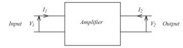
(In point of fact the box could represent any system having a single input and
single output.) Note the convention assumed for the positive direction of
currents and voltages. In particular, observe the directions I 1 and I 2. It is the
accepted convention to have both currents flowing into the box. Note also that
the subscript notation '1' for input and '2' for output is used.
We have said that in the common emitter amplifier, the base is input, the
collector the output and the emitter is common to both input and output. The
transistor can therefore be pictured connected within the box as shown in the figure below
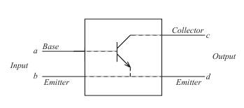
Thus, the transistor can be represented by a two port (input port and output
port), four terminal (a,b,c,d) box by extending the emitter from input to output.
Note also, in the black box approach, only signals (i.e. input and output
voltages and currents) are shown. No attempt is made to show power supplies
and the like, which are taken for granted.