2015-04-30
 391
391- · Минимальный просвет 2.4 м, без препятствий.
- · Должна быть обеспечена защита от загрязнений.
- · Необходим доступ к магистральным трассам.
- · Работа системы отопления, вентиляции и кондиционирования воздуха (HVAC) - 24 часа в сутки, 365 дней в году.
- · Контролируемый диапазон температуры и влажности - 18° C - 24°C, 30% - 55%, относительная влажность измеряется на высоте 1.5 м над уровнем пола.
- · Должен быть обеспечен отдельный контур электрического питания, терминированный на собственном щитке.
- · Минимальный уровень освещенности должен составлять 500 лк. Выключатель должен быть расположен рядом с входной дверью комнаты.
- · Минимальные размеры двери - такие же, как для телекоммуникационного шкафа. Рекомендуются двойные двери без центрального упора и порожка.
ГОРОДСКОЙ ВВОД
Состоит из ввода телекоммуникационных служб в здание и магистральных трасс между зданиями.
Расположение
- Необходимо связаться с поставщиками телекоммуникационных услуг для выяснения требований.
- При размещении городского ввода необходимо учитывать расположение других служб.
- В случае необходимости в обеспечении безопасности, непрерывности сервиса или других специальных функциях должен быть установлен альтернативный дополнительный городской ввод.
- Оборудование, не относящееся к поддержке городского ввода, не должно устанавливаться, проходить через или входить в помещение телекоммуникационного ввода.
- · Ввод должен размещаться в сухом месте, не подверженном затоплению, как можно ближе к точке ввода в здание и главной электрощитовой.
Особенности проектирования
- Соответствует требованиям к сейсмическим зонам.
- Трасса городского ввода должна относиться к одному из следующих типов: подземная, зарытая, воздушная, тоннельная.
- Как минимум одна стена должна быть покрыта жестко закрепленной панелью (фанера, ДСП) толщиной 20 мм.
- Минимальный уровень освещенности - как для телекоммуникационного шкафа.
- Использование фальш-потолков не допускается.
- Минимальные размеры двери - как для телекоммуникационного шкафа.
- Электрическое питание - как для телекоммуникационного шкафа. О бытовых розетках не упоминается.
- Заземление - как для телекоммуникационного шкафа.
РАЗНОЕ
- Пожарная безопасность обеспечивается в соответствии с применимыми инструкциями
- Изоляция горизонтальной трассы от источников электромагнитных помех (EMI):
- Необходимо разделение телекоммуникационных и силовых кабелей (Статья 800.52 ANSI/NFPA 70)
- Здание должно быть защищено от молний (ANSI/NFPA 780 (Ref D.4)
- Необходима защита от пиковых перенапряжений (Статья 280 ANSI/NFPA 70 и 9.11 ANSI/IEEE 1100 [Ref D.1])
- Должна быть обеспечена система заземления (ANSI/TIA/EIA-607)
- Необходимо своевременное устранение неисправностей проводки (Раздел 7.5 ANSI/IEEE 1100) - Снижение уровня наводимых шумов:
- Увеличение разделения с источниками шумов
- Проводники электрических фидеров, нейтрали и заземления должны быть расположены близко друг к другу
- Обеспечьте защиту от перенапряжений в цепях сети
- Используйте полностью закрытую заземленную металлическую трассу или размещайте кабельную систему рядом с заземленной металлической поверхностью
Standards Update

The TIA and ISO Standards development bodies have spent the last months finalizing details on new generic requirements for high bandwidth cabling in preparation for their technical review by the industry. This is no small feat considering the fact that category 6 and 7 cabling offers two and six times the bandwidth capacity of category 5e, respectively. Couple these twisted-pair cabling advances with the revolutionary improvements that have been realized in fiber connectivity and it’s clear to see that the Standards have armed the end-user with cabling solutions that will support even the most extreme network demands.
Couple the advances of twisted-pair cabling with the
revolutionary improvements that have been realized
in fiber connectivity and it's clear to see that the Standards
have armed the end-user with cabling solutions that will
support even the most extreme network demands.
Category 6 & Category 7
Historically, information transmission rates double every 18 to 24 months. To support this growth, in September of 1997, ISO began formalizing per-formance criteria for cabling systems designed to support positive power sum attenuation-to-crosstalk (PSACR) values to 200 MHz (category 6/class E) and 600 MHz (category 7/class F). At that time, TIA also recognized the urgent demand for a high bandwidth unshielded twisted-pair cabling solution and began concurrent development on category 6. Although TIA has not initiated development of a category 7 solution, there is significant harmonization between the status of the TIA category 6 and ISO class E draft Standards. The latest revisions of the working documents are shown in Table 1.
Table 1
| Latest Industry Category 6/Class E and Category 7/Class F Draft Standards | |
| TIA Draft Standards | ISO Draft Standards |
| Category 6 Transmission Performance Specifications for 4-Pair 100 ohm Category 6 Cabling | Class E & Class F ISO/IEC 11801 2nd Edition Customer Premise Cabling |
| Draft 6 - April, 2000 | N598 - May, 2000 |
| Prepared by: TR-42.7.1 Copper Cabling Systems Working Group | Prepared by: ISO/IEC JTC 1/SC 25/WG 3 |
| Category 7 Not under developement at this time. |
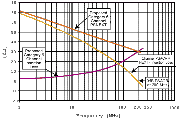
It is interesting to note that, although the positive PSACR frequency for category 6/class E cabling systems is 200 MHz, due to considerations such as equipment crosstalk cancellation capability, both TIA and ISO will be characterizing these cabling systems to 250 MHz. At this time, ISO class F is characterized to an upper frequency value of 600 MHz.
In conjunction with the cabling objectives outlined in 1997, TIA and ISO have implemented provisions into their draft Standards to ensure that category6/class E and category 7/class F cabling systems will work in harmony with existing generic infrastructures. The achieve this, systems and components are required to be backward compatible with existing categories and classes, as well as be interoperable with components of like categories from different manufacturers. TIA has since devised a test method that provides a benchmark against which active equipment and systems manufacturers can qualify their category 6 plugs and sockets. Compliance to these provisions ensures component interoperability and backward compatibility. Work on a category 7 plug and socket requirement is still pending the final outcome of the ISO/IEC category 7 connecting hardware interface selection process.
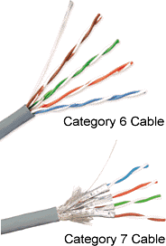
The significant differentiator between category 6/class E and category 7/class F is the cabling media. Category 6/class E is generally considered to represent the highest bandwidth capable of being supported by unshielded twisted-pair (UTP) and screened twisted-pair (ScTP) cables; to achieve even greater performance, category 7 cables must utilize a more robust, fully shielded construction which virtually eliminates crosstalk between all pairs up to 600 MHz (see Figure 2). A typical category 7 cable design consists of four 23 AWG (0.55mm) twisted-pairs, each enveloped within a foil wrap. An overall braided sheath typically surrounds the four foil-wrapped pairs. A drain wire may be provided to facilitate grounding. Category 7 fully shielded cable types are sometimes referred to as SSTP (“double shielded twisted-pair”) or PiMF (“pairs in metal foil”).
| Figure 1 - Category 6 Channel PSACR |
|
Although any compliant connecting hardware design may be used at the cross-connect and consolidation/ transition point connections, the connecting hardware interface at the work area has been traditionally defined as an 8-position modular or “RJ-style” interface. This has been done to ensure that the end-user is not subjected to interface designs with uncontrolled fit and dimension. The TIA and ISO communities have agreed that the standard 8 position modular plug/outlet connection will still be specified to support proposed category 6/class E cabling at the telecommunications outlet. Ideally, the ISO Standards development committee would prefer to maintain this interface in their specification of category 7/class F cabling systems as well. However, due to backward compatibility and interoperability concerns, some industry experts considered a category 7 “RJ-style” interface unachievable in a practical operating environment.
Category 6/class E is generally considered to represent the
highest bandwidth capable of being supported by unshielded
twisted-pair (UTP) and screened twisted-pair (ScTP) cables; to
achieve even greater performance, category 7 cables must utilize
a more robust, fully shielded construction which virtually eliminates
crosstalk between all pairs up to 600 MHz.
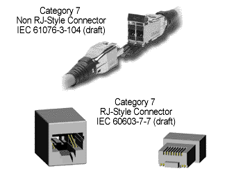
As a result, the ISO/IEC/ SC 48/WG 3 technical committee began investigating the capabilities of both an “RJ-style” and a “non RJ-style” connector for use at the work area. In June of 1999, the technical committee selected an “RJ-style” category 7 connector design and The Siemon Company’s TERA™ (as the fallback “non RJ-style” category 7 connector design (see Figure 3).
| Figure 2 - Cable Media |
|
| Category 6 cable is similar in construction to category 5e cable. The exception is that most category 6 cables have a center filler that separates each pair within the jacket. Category 7 cable is of a different construction than category 5e or 6 cable. Not only is there an overall braid and/or foil around all four pairs, but each pair is individually wrapped in foil. |
In the event that the performance feasibility of the “RJ-style” design is not validated, the technical committee will select the Siemon TERA™ as the category 7 Standard’s specified work area interface. Regardless of which design is chosen, the committee is chartered to specify complete category 7 work area interface criteria addressing dimensional, transmission, electrical, mechanical, and reliability characteristics by the first quarter of 2001.
The construction of the category 7/ class F media offers some significant performance advantages, particularly with respect to crosstalk, over category 6/ class E cabling. Table 2 provides the latest draft channel requirements provided by TIA and ISO for their next generation of cabling. The third column in the table provides an indication of the signal performance improvement, in volts, realized by category 7/class F cabling over category 6/class E cabling.
At this time, the channel and permanent link performance values for category 6/class E and category 7/class F are firm and unlikely to undergo significant revisions The released TIA and ISO Standards are also expected to specify laboratory test and field verification methods, installation practices, and other considerations such as reliability and durability in addition to transmission performance. The few remaining items that need to be addressed prior to standard publication are generally related to these topics. Table 3 provides a list of items that are still under study by these groups.
The short list of remaining items under study means that the task of developing the category 6/class E and category 7/class F Standards is drawing to a close. At this time, the ISO committee has already processed comments on two drafts of the ISO/IEC 11801 2nd edition and TIA is gearing up to present their draft category 6 Standard for industry ballot review in September of 2000. Barring any unforeseen technical issues, it is likely that TIA and ISO approved category 6/ class E and category 7/class F Standards will be available to the industry in 2001.
| Figure 3 - "Non RJ-Style" and "RJ-Style" Category 7 Connectors |
|
| Siemon’s TERA™ connector has been accepted as the “non RJ-style” category 7 interface. The ”RJ-style” category 7 interface is in development and uses four additional pins in the outlet and plug as seen above. |