2015-08-21
 415
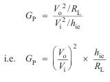
415The power gain is defined as
There are, however, a number of ways in which we could evaluate power gain.
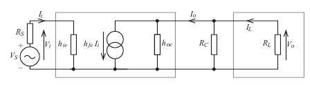
Consider the circuit below; note that h oe and R c have again been shown separately.
We can define the power gain as
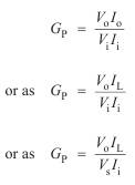
All these definitions are perfectly valid; which one is chosen depends upon
which aspect of the circuit's performance we wish to evaluate.
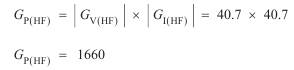
If we calculate the power gain as
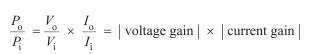
then, having found G V and G I, finding the power gain is straightforward.
Note also that 
 which offers an alternative method
of calculating the power gain:
One final word of caution! In the above discussion on power gain we have
assumed that the load is resistive. If, however, this is not the case, then due
regard must be paid to the phase relationship between voltage and current.
Let’s consider the example.
For the equivalent circuit shown
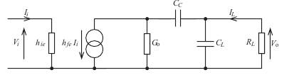
CL = 10 nF hfe = 100
RL= 1 kW hie= 1 kW G o = 10 –4 S CC = 10 mF
calculate:
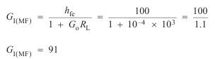
(i)the mid-band current gain (I L/ I i)
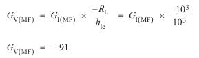
(ii) the mid-band voltage gain (V o/ V i)
(ii) the mid-band power gain (power in load/power input)
(iv) the lower half-power frequency
(v) the upper half-power frequency
(vi) the bandwidth
(vii) The magnitudes of the current and voltage gains and the power gain
at w = 220 ´ 103 rad s–1.
(i) Mid-band current gain
(ii) Mid-band voltage gain
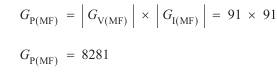
(iii)Power gain
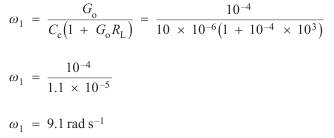
(iv) Lower half-power frequency
f1=w1/2p=9.1/2p=1.45 Hz
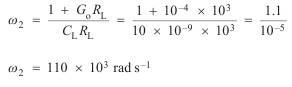
(v)Upper half-power frequency
f2=w2/2p=17.5 kHz
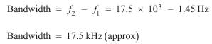
(vi)
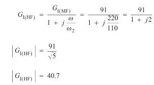
(vii) As 220 ´ 103 rad s–1 > w2, we must use the high frequency equations for
G I and G V.
Current gain
Voltage gain
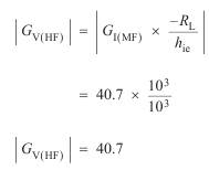
Power gain
Again, as the power gain has been defined as  where I L is
the current through a resistive load, we can write