2015-08-21
 565
565
|
|

|
|
|
|


|
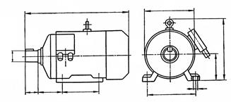
| Type designation | Number of poles | Overall dimensions | Mounting dimensions | ||||||||
| L | H | D | d | h 1 | l 1 | l 2 | l 3 | b | d 1 | ||
| 4A90L | 2;4;6;8 | ||||||||||
| 4A100S | |||||||||||
| 4A100L | |||||||||||
| 4A112M | |||||||||||
| 4A132S | |||||||||||
| 4A132M | |||||||||||
| 4A160S | |||||||||||
| 4;6;8 | |||||||||||
| 4A160M | |||||||||||
| 4;6;8 |
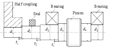
Fig.9.1. Input shaft
Table 9.2
Recommended values of t 1 and t 2
| d, mm | 20 - 50 | 55 - 120 |
| t 1, mm | 2; 2.5 | |
| t 2, mm | 1; 1.5 | 2.5 |
The next portion of the shaft is for mounting a bearing. The diameter of this portion is determined as
d 3 = d 2 + 2∙ t 2,
where t 2 is the height of the shoulder that is used for differentiation of shaft surfaces by hardness and roughness. Recommended values of t 2 are given in table 9.2. It is necessary to note that t2 should be chosen to obtain shaft diameter d3 ended by 0 or 5. It is explained by the fact that bearings are standard elements with the inner ring diameter ended by 0 or 5.
Bearings must be fixed in the axial direction. That is why the diameter of the next portion of the shaft, where a pinion or gear is installed, is determined as
d 4 = d 3 + 2∙ t 1.
Obtained value of d4 should correspond to standard series.
A pinion may be made either as solid with the shaft or as an individual part. In order to increase shaft strength and rigidity it is recommended to use pinion shafts.
The last portion of the shaft is for installing the second bearing. The diameter of this portion should be the same as for the first bearing. In our case it is d 3.
The output shaft has the same design as the input one. But in contrast to the latter a gear is mounted on the shaft portion of diameter d 4 (Fig.9.2). In order to fix the gear in the axial direction we should provide for the shoulder of height t 1. That is why the diameter of the next portion of the shaft is d 5 = d 4 + 2∙ t 1.
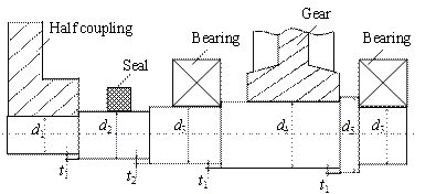
Fig.9.2. Output shaft
For our case we should design the output shaft where a helical spur gear is mounted. We will have the following diameters:
 ,
,
Let us assume dmin = d 1 = 50 mm (according to the standard series);
d 2 = d 1 + 2∙ t 1 = 50 + 2∙ 2.5 =55 mm;
d 3 = d 2 + 2∙ t 2= 55 + 2∙ 2.5 = 60 mm;
d 4 = d 3 + 2∙ t 1= 60 + 2∙ 5 = 70 mm;
d 5 = d4 + 2∙ t 1= 70 + 2∙5 = 80 mm.
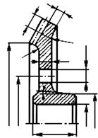
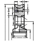
For bevel pinion shafts (Fig.9.3) and worm shafts (Fig.9.4) we should introduce the additional portion of diameter d 2' between portions of diameters d2 and d3. This portion is necessary to install a slotted nut for adjusting clearances in the bearing. Diameter d 2' should be chosen according to table 12.1.
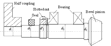
Fig.9.3. Bevel pinion shaft
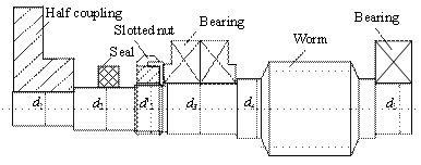
Fig.9.4. Worm shaft
9.3. Determine sizes of elements that are mounted on the shaft.
9.3.1. Pinion.
Face width of the pinion bp = bg + 5.
9.3.2. Spur and bevel gears (Fig.9.5, a, b)
- thickness of the rim δ = (3…4)· m;
- thickness of the web C = (0.2…0.3)· bg;
- diameter of the hub dhub =(1.5…1.7)· dshaft;
- length of the hub lhub =(1.2…1.5)· dshaft;
- diameter of the hole  ;
;
- diameter of the hole centre line  ;
;
- fillet radii R ≥ 6 mm and angle γ ≥ 7º.
|


|

|
|


|

|


|
|

|
|


|
|
|

|
|
|

|


a b c
Fig.9.5. Spur gear (a), bevel gear (b), worm gear (c)
9.3.3. Worm gear (Fig 9.5, c).
- thickness of the bronze ring δ1= 2· m;
- thickness of the steel rim δ2= 2· m;
- thickness of the web C = (0.2…0.3)· bg;
- diameter of the hub dhub =(1.5…1.7)· dshaft;
- length of the hub lhub =(1.2…1.5)· dshaft;
- diameter of the screw ds =(1.2…1.4)· m;
- length of the screw ls =(0.3…0.4)· bg;
- diameter of the hole  ;
;
- diameter of the hole centre line  ;
;
- width and height of the collar h =0.15· bg; t = 0.8· h
- fillet radii R ≥ 6 mm and angle γ ≥ 7º.
9.3.4. Bearings.
The type of a bearing depends on the load it can withstand.
Shafts where straight spur gears are located should be installed in bearings that withstand radial load only. For this purpose we use radial ball bearings of lightweight series (table 9.3).
Shafts of helical spur gears should be mounted on angular contact ball bearings of lightweight series (table 9.4) because they can perceive both radial and axial loads.
Shafts of bevel gears and a worm gear are mounted on tapered roller bearings of lightweight series (table 9.5). It is explained by the fact that they can withstand heavy axial loads.
Worm shafts are installed in two tapered roller bearings (table 9.5) and one radial ball bearing of lightweight series (table 9.3).
Table 9.3
Single - Row Radial Ball Bearings (GOST 8338-75). Lightweight series
dc = 0.5∙(D+d)
Dw = 0.32∙(D-d)
S = 0.15∙(D-d)
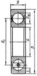
| Type designation | d | D | B | r | Basic load rating Cr, kN | Static load rating C 0, kN |
| 5.9 | 2.65 | ||||||
| 6.89 | 3.1 | ||||||
| 7.8 | 3.55 | ||||||
| 9.56 | 4.5 | ||||||
| 1.5 | 12.7 | 6.2 | |||||
| 1.5 | 14.0 | 6.95 | |||||
| 1.5 | 19.5 | 10.0 | |||||
| 25.5 | 13.7 | ||||||
| 32.0 | 17.8 | ||||||
| 33.2 | 18.6 | ||||||
| 35.1 | 19.8 | ||||||
| 2.5 | 43.6 | 25.0 | |||||
| 2.5 | 52.0 | 31.0 | |||||
| 2.5 | 56.0 | 34.0 | |||||
| 2.5 | 61.8 | 37.5 | |||||
| 2.5 | 66.3 | 41.0 | |||||
| 70.2 | 45.0 | ||||||
| 83.2 | 53.0 | ||||||
| 95.6 | 62.0 | ||||||
| 3.5 | 108.0 | 69.5 | |||||
| 3.5 | 124.0 | 79.0 |
Table 9.4
Single-row angular-contact ball bearing (GOST 831-75). Lightweight narrow series (a=12° for 36000 and a=26° for 46000)
dc = 0.5∙(D+d)
Dw = 0.32∙(D-d)
S = 0.15∙(D-d)  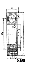
| Type designation | d | D | B | T | r | r 1 | Load rating, kN |
| Cr | C 0 | |||||||
| 1.5 | 0.5 | 15.7 | 8.31 | |||||
| 1.5 | 0.5 | 16.7 | 9.10 | |||||
| 1.5 | 0.5 | 22.0 | 12.0 | |||||
| 30.8 | 17.8 | |||||||
| 38.9 | 23.2 | |||||||
| 41.2 | 25.1 | |||||||
| 43.2 | 27.0 | |||||||
| 2.5 | 1.2 | 58.4 | 34.2 | |||||
| 2.5 | 1.2 | 61.5 | 39.3 | |||||
| 2.5 | 1.2 | 69.4 | 46.8 | |||||
| 2.5 | 1.2 | 80.2 | 54.8 | |||||
| 2.5 | 1.2 | 78.4 | 53.8 | |||||
| 1.5 | 93.6 | 65.0 | ||||||
| 1.5 | 101.0 | 70.8 | ||||||
| 1.5 | 118.0 | 83.0 | ||||||
| 3.5 | 134.0 | 95.0 | ||||||
| 3.5 | ||||||||
| 3.5 |