2015-08-21
 308
308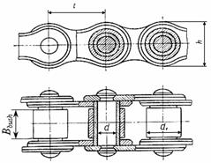
| Pitch t | Bbush, mm | Pin diameter d | Roller diameter d1 | h, max | b, max | Breaking load Fbr, kN | Mass per meter run q, kg | Projected hinge area Sh, mm2 |
| 9.525 | 5.72 | 3.28 | 6.35 | 8.5 | 9.1 | 0.45 | 28.1 | |
| 12.7 | 7.75 | 4.45 | 8.51 | 11.8 | 18.2 | 0.75 | 39.6 | |
| 15.875 | 9.65 | 5.08 | 10.16 | 14.8 | 22.7 | 1.0 | 54.8 | |
| 19.05 | 12.7 | 5.96 | 11.91 | 18.2 | 31.8 | 1.9 | 105.8 | |
| 25.4 | 15.88 | 7.95 | 15.88 | 24.2 | 60.0 | 2.6 | 179.7 | |
| 31.75 | 19.05 | 9.55 | 19.05 | 30.2 | 88.5 | 3.8 | ||
| 38.1 | 25.4 | 11.12 | 22.23 | 36.2 | 127.0 | 5.5 | ||
| 44.45 | 25.4 | 12.72 | 25.4 | 42.4 | 172.4 | 7.5 | ||
| 50.8 | 31.75 | 14.29 | 28.58 | 48.3 | 226.8 | 9.7 |
8.14. Determine the web thickness of sprocket
C = 0.93∙Bbush= 0.93∙19.05 = 17.72mm
where Bbush is determined according to table 8.2.
8.15. Determine forces acting to the links
- turning force  ;
;
- centrifugal force Fc = q ×V2= 3.8 × 1.682 = 10.73 N, where q is the mass per meter run of the chain in kg (table 8.2);
- load due to chain deflection Ff = 9.81× Kf××q×a, where Kf =1 for vertical centre line arrangements, Kf = 6 for horizontal centre line arrangements and Kf = 1.5 for the centre line arrangement on the angle 45o.
In our case centre line is arranged on the angle 45o, thus Kf = 1.5
Ff = 9.81× 1.5 × 3.8 × 1.423 = 79.57 N.
8.16. Determine the design load on the shaft
Fshaft = Ft + 2∙Ff = 3539.88 + 2 ∙ 79.57 = 3699.02 N.
8.17. Determine the safety factor
 ,
,
where Fbr is the breaking load in N(table 8.2); K is the dynamic factor taking into account the load nature (p.8.4); [S] is standard safety factor (table 8.3).