Values of temperature factor Kt
| Temperature of the bearing t, ºC | |||||||
| Kt | 1.0 | 1.05 | 1.1 | 1.15 | 1.25 | 1.35 | 1.4 |
As a rule in general purpose speed reducers the working temperature of bearings is less than 100 ºC.
11.6. Determine the radial force factor X and axial force factor Y for both supports. For this purpose it is necessary to find ratio  for every support and compare with axial load parameter e.
If  then Xi =1 and Yi = 0. Otherwise Xi and Yi are determined according to table 11.1.
In our case: V =1; Ks =1.3; Kt =1;  > e, then X1 =0.45 and Y1 = 1.81;
  = e, then X2 =1 and Y2 = 0.
11.7. Determine the equivalent radial loads for both supports
Pr 1 = (X 1× V×Fr 1 + Y 1× Fa 1)× Ks×Kt =(0.45∙1∙7491.6+1.81∙2614.4)∙1.3∙1=10530 N,
Pr 2 = (X 2× V×Fr 2 + Y 2× Fa 2)× Ks×Kt = (1∙1∙9870.2+0∙2961.1)∙1.3∙1=12831 N.
11.8. Determine the rated life in million revolutions for the most loaded support
 ,
,
where m = 3 for ball bearings and m =  for roller bearings.
11.9. Determine the rated life in hours
 .
.
For general purpose speed reducers Lh min=12000 hours.
If the last inequality is not carried out it is necessary to reselect the bearing of more heavy series and make all calculations once more.
In our case  . Condition is satisfied and we can use this type of bearings.
12. Designing the gear speed reducer
12.1. Design supports of the speed reducer shafts
Normal operation of bearings depends upon the arrangement of bearings on the shaft as well as the method of fixation of the shaft in the axial direction.
According to fixation of the shaft in the axial direction there are fixed support and floating support.
Depending upon arrangement of bearings we will distinguish between inward (face to face) arrangement and arrangement with the fixed and the floating supports. Sometimes outward (back to back) arrangement of bearings is used too (for example, for bevel pinion shafts).
Let us consider features of all arrangements.
Inward arrangement of bearings.
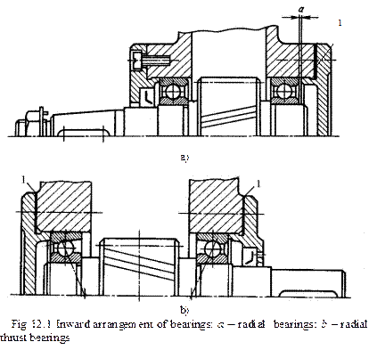
This is the most popular arrangement according to which a shaft is fixed in the axial direction in both supports. Every support withstands one-sided axial load. The inner ring of both bearings rests against the shoulder made on the shaft or against the end face of other component installed on the shaft. In its turn, the outer ring of bearings rests against the end face of a cap or other part secured in the casing (Fig. 12.1).
The inward arrangement is simple in construction and permits easy adjustment of bearings. But there exists a risk that the shaft can be seized at supports. It is explained by the fact that during operation of bearings, shafts and casings heat up. As a result, radial clearances in bearings decrease. Also, the shaft length increases on heating, which reduces the axial clearance in bearings.
For safeguard against seizure we should provide small clearance a at one end of the shaft between the outer ring of the bearing and the end face of the cap (Fig. 12.1, a). This clearance is very small (0.2…0.5 mm). That is why it is not shown in the drawing. In order to adjust this clearance we use either thin metal shims 1 placed between the casing and the flanged cap at one end of the shaft or a spacer ring installed between the end face of the embedded cap and the outer ring of the bearing.
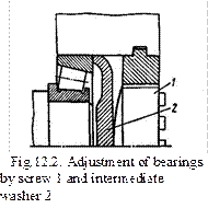
In radial-thrust bearings (angular contact ball bearings and tapered roller bearings) there exist radial clearances between rolling elements and both rings that may be adjusted in assembly. We can achieve adjustment of these clearances by means of thin metal shims1 mounted between the casing and flanges of caps at both ends of the shaft (Fig. 12.1, b). If we have embedded caps needed adjustment is achieved by screw 1 and intermediate washer 2 (Fig. 12.2).

 In this case the threaded element simplifies adjustment because caps need not be removed to replace the shims but the bearing assembly becomes more elaborate.
Inward arrangement of bearings is used for shafts of straight spur gears, helical spur gears, bevel gear and worm gear.
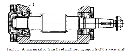
Bearings of the worm shaft are arranged as fixed and floating supports (Fig. 12.3).
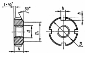
The fixed support consists of two inward facing  radial thrust bearings (as a rule tapered roller bearings) mounted in the bearing housing. Outer and inner rings of the fixed support should be fixed in both axial directions. That is why the fixed support can withstand double-sided axial load. In order to adjust radial clearances in tapered roller bearings we use slotted nut (table 12.1.) and lock-washer (table 12.2).
 Floating support is used to compensate thermal deformations of the shaft and manufacturing errors. We use as floating support a radial ball bearing which inner ring is fixed in both axial directions and outer ring is left free. For fixation of the inner ring we employ either end plates (table 13.3, 13.4), or slotted nuts with lock washers, or spring ring.
The rightness of the worm engagement is adjusted by means of metal shims 1 (Fig. 12.3) mounted between the casing and the flange of the housing.
Supports of the bevel pinion shaft are installed in the housing according to outward arrangement (Fig. 12.4). In this case we obtain the minimum bending moment developing on the shaft. In order to adjust radial clearances in bearings we should use a slotted nut with a lock-washer. Rightness of the bevel gear engagement is adjusted by metal shims 1 (Fig. 12.4) mounted between the casing and the housing flange.
Table 12.1
 Standard slotted nuts (GOST 11871-88)
| Thread diameter, d | Thread pitch | D | D1 | H | b | h |
| 1.5 | 2.5 | |||||
Table 12.2
 2015-08-21
 471
471


