2015-08-13
 491
4911. On the task of teacher to execute assembling sketches of inductor and armature of electric machine, marking on them by numbers basic units of design.
2. To do on the teacher task sketches of separate units of design of list, marked by numbers on the assembling sketch.
3. To describe the purpose of all electric machine design units, marked by numbers on the assembling sketches.
Contents of a report
The report must contain.
1. Aim of work.
2. Assembling sketches of inductor and armature of electric machine.
3. Sketches of separate design units.
4. Brief sketch of design units and their purpose.
5. Electric circuits of machine excitation (on the task of teacher).
Control questions
1. What aim the units of EEC magnetic core are made of steel alloys?
2. What basic units does any electric machine consist of? What purpose of these units?
3. Whether the notions "inductor" and "stator", "armature" and "rotor" are equivalent?
4. What design unit is inherent only for the direct current EEC?
5. What aim the magnetic core active units are made laminated with?
6. What designs of synchronous EEC are called inverted?
7. What excitation charts of synchronous EEC do you know? What advantages and lacks of these charts?
8. Re-count basic units of contactless synchronous EEC.
9. What types of asynchronous EEC do you know? What advantages of asynchronous EEC with the short-circuited rotors?
10. Name basic design units of asynchronous EEC with the hollow rotor.
Laboratory work 1
RESEARCH OF SINGLE-PHASE TRANSFORMER
Aim of work
Study of design, operation principle, properties and descriptions of transformer. Carrying out the tests of open and short circuit, determination of basic parameters and graphing of responses of transformer.
Theory
The transformer is a static electromagnetic device, which converts electromagnetic energy of alternating current (AC) of one voltage into electromagnetic energy of AC of other voltage of the same frequency.
Structurally a transformer consists of closed core, assembled of electrical engineering steel sheets. Inductively coupled windings are coiled round the core.
Transformers are divided into single-phase and three-phase. The simplest is a transformer with one primary and one secondary windings. Schematically a single-phase double-wound transformer is represented on a fig. 1.1.
The operation mode of transformer at which AC voltage U 1 is supplied to its primary winding and a secondary winding is broken, is called open-circuit. Under the action of voltage U 1 the alternating current і 1 arises in a primary winding, which creates magnetizing force (MF), which equales to i 1 w 1, where w 1 − turns quantity of primary winding. This MF creates alternate magnetic flux, which consists of basic flux Ф and leakage flux Фσ1.
A basic magnetic flux Ф is fully closed up along ferromagnetic core and that is why coupled with the turnes of both windings. Leakage flux Фσ1 is closed up only round the turns of primary winding.
By electromagnetic induction law the basic magnetic flux Ф induces in both transformer windings ЕMFs, instantaneous values of which are equal to: e 1 = − w 1∙ d Ф / dt; e 2 = − w 2∙ d Ф / dt,
where w 2 – turns quantity of secondary winding.
The effective values of EMF, induced in transformer windings are equal to:
E 1 = (2π/√2)∙ f∙w 1 ∙ Ф max = 4,44∙ f∙w 1 ∙ Ф max;
E 2 = (2π/√2)∙ f∙w 2 ∙ Ф max = 4,44∙ f∙w 2 ∙ Ф max;
where Ф max − maximal value of basic magnetic flux; f − frequency of current in a network.
Ratio of effective or maximal values of EMF, induced by a basic magnetic fluxes, is called the transformer factor
k = E 1 / E 2 = (4,44∙ f∙w 1 ∙ Ф max) / (4,44∙ f∙w 2 ∙ Ф max) = w 1 / w 2.
Leakage flux Фσ1 causes appearance of EMF only in a primary winding. Effect of this EMF, marked е σ1, is taken into account by inductive resistance, which equals to X 1 = ω∙ L σ1, so at a sinusoidal current effective value of this EMF: Е σ1 = Х 1 І 1, where L σ1 − inductance of primary winding, which corresponds to leakage flux Фσ1 (inductance of leakage); ω = 2π f – angular speed of current. So as the linkage flux Фσ1 passes a considerable part of path in air, permeance of which unchanging, then L σ1 = const.
By Kirchhoff’s second law for a primary circle:
u 1 + e 1 + e σ1 = R 1 ∙i 1,(1.1)
where R 1 − active resistance of primary winding.
At open circuit of transformer a current in primary winding is called the current of idling and mark і 0.
It is possible equation (1.1) (equation of EMF equilibrium of primary circle of transformer) to write down in a complex form:
U 1 = − E 1 + R 1 ∙ I 1 + jX 1 ∙ I 1 = − E 1 + Z 1 ∙ I 1, where Z 1 = R 1 + jX 1. Thus, it be possible to say, that supplied voltage U 1 is balanced by EMF E 1, induced by a basic magnetic flux, and voltage drop across active resistance R 1 and inductive resistance X 1 of winding, conditioned by the leakage flux Фσ1 and that is why is called by leakage inductive resistance of primary winding.
At open circuit a voltage drop across R 1 and Х 1 is small, as open circuit current І 0 makes up only 3…8 % of the nominal current І 1 nom
U 1 ≈ E 1
Voltage at the terminals of the broken secondary winding U 20 equals to electromotive force Е 2, as І 2 = 0:
U 20 = Е 2
Therefore k = E 1 / Е 2 ≈ U 1 / U 20.
The operation mode of transformer at loading of secondary winding is called an operating duty. The secondary circle of transformer is here closed and a current і 2 arises in it under the action of EMF е 2.
An active power of the secondary winding of transformer which is consumed by user, equals to:
Р 2 = U 2∙ І 2 соs φ2,
where U 2 and І 2 − accordingly effective values of voltage at the terminals of secondary winding and current in it; соs φ2 − power-factor of load.
Windings of transformer does not have an electric contact between themselfs. The transmission of energy in the secondary circle of transformer is carried out by the alternating magnetic field, concentrated in a core.
In the operating duty of transformer the secondary current і 2, like primary, creates the leakage flux Фσ2, which is closed up only round the turnes of secondary winding and induces in it EMF е σ2. Effect of this EMF is taken into account by inductive resistance Х 2 = ω∙ L σ2, so an effective value of this EMF: Е σ2 = X 2∙ I 2, where L σ2 – leakage inductance of secondary winding of transformer. As well as leakage inductance of L σ1 the inductance of L σ2 = const.
Equation of EMF equilibrium in the secondary circle of transformer is such:
e 2 + e σ2 = u 2 + R 2∙ i 2.
Accordingly:
U 2 = E 2 − R 2∙ I 2 − jХ 2∙ I 2 = Е 2 – Z 2∙ I 2,
where Z 2 = R 2 + jХ 2; R 2 − active resistance of secondary winding.
The increase of transformer load results in the increase of current in the secondary circle I 2. However (in accordance with Lentz’s principle) the increase of secondary current results in diminishing of magnetic flux Ф in the core, as created by the current і 2 a magnetizing force w 2∙ i 2 is almost in antiphase to force w 1∙ i 1, which is created by a primary current. With diminishing of magnetic flux in a core the induced EMF е 1 must diminish, that counteracts to the brought voltage U 1. It causes the increase of primary current І 1 automatically, and at the same time increase of magnetic flux in a core and EMF Е 1. In a result, a basic magnetic flux remains almost constant (Ф max = const) both at idling and at the nominal loading, only if voltage U 1 and frequency f 1 does not change, id est the common action of magnetizing forces of both windings in an operating duty is almost equivalent to the action of magnetizing force of one primary winding at idling:
w 1 ∙i 1 + w 2 ∙i 2 = w 1 ∙i 0 or w 1 ∙ І 1 + w 2 ∙ І 2 = w 1 ∙ І 0
Really, through the small voltage drops across resistance r 1 and х 1 in the range of the rated load U 1 ≈ E 1 and Ф max ≈ U 1 / (4 44∙ f 1∙ w 1). Thus, at U 1 = const and f 1 = const, a flux Ф max ≈ const.
Operation of transformer is accompanied by the losses of powers, which are spent on heating of windings and core. The power losses in a transformer are divided into constant, that do not depend on load, and variables. Variable losses are losses in transformer windings, which are called also losses in a copper:
Δ PCp = R 1∙ I 12 + R 2∙ I 22
Constant losses in a core are called losses in a steel. They consist of losses on remagnetization (hysteresis) and on eddy currents:
Δ Рst = Δ Рh + Δ Рec,
where Δ Рh − losses on hysteresis; Δ Рec, − losses on eddy currents.
Losses of power in steel at the set frequency are proportional approximately to the square of magnetic induction in a core, and thus to the square of voltage U 1. At the same supply voltage U 1 these losses remain almost identical both at idling and at the nominal load.
The efficiency of transformer operation is characterized by an output-input ratio:
η = Р 2 / Р 1 = (U 2∙ І 2 соs φ2) / (U 1∙ І 1 соs φ1) = Р 2 / (Р 2 + Δ PM + Δ Рst)
where Р 1 = U 1∙ І 1∙ соs φ1 − active-power which is consumed by a transformer from a network.
Transformers are characterized by high enough values of efficiency, which in powerful transformers reach 98…99%. In low-powered transformers efficiency can go down to 50…70%.
If to neglect losses of power, it is possible to accept, that power, brought to the transformer, equals to the output power:
Е 1∙ I 1 ≈ E 2∙ I 2
From where: I 2 / I 1 = Е 1 / Е 2 = w 1 / w 2 = k and I 1 = I 2 / k.
Processes which take place in a transformer can be analysed by means of electric charts, made thus, that in a power relation they were equivalence to the transformers. One of such charts is shown on fig. 1.2.
Passing to the substitution chart is carried out by reduction of secondary winding of transformer to primary. Thus allow, that primary and secondary windings of transformer have an identical quantity of turns. All other values are accordingly changed thus, that in a power relation this reduced transformer was equivalent to the actual transformer.
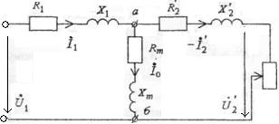
Fig. 1.2
Values that behave to the reduced secondary winding are called reduced and marked by the same symbols with a stroke above:
w '2 = k∙w 2 = w 1; Е '2 = k∙Е 2 = Е 1; R’ 2 = k2R2; Z’L = k2 ZL; I’ 2 = I 2 / k,
where k = w 1 /w 2; Z’L − impedance of load.
Basic equations, equated for an equivalent electric circuit under Kirchhoff’s laws, look like:
U 1 = − E 1 + Z 1 ∙ I 1;
U ’ 2 = E ’ 2 − Z 2∙ I ’ 2 = Z L∙ I ’ 2;
I 1 = I 0 + (− I ’ 2).
Active resistance Rm in the equivalent circuit is such, that thermal losses in it equal to losses in the real transformer core. EMF Е 1, that is induced in the primary winding by a basic magnetic flux and equal to it reduced EMF of secondary winding Е '2, correspond to equivalent voltage drop across Zm = √(R 2 m + X 2 m) in the equivalent circuit. A resistance Хm corresponds to basic magnetic flux. Branch of equivalent circuit аb with resistances Rm and Хm is called magnetizing.
The parameters of equivalent circuit of a transformer and its efficiency can be defined by results of two experiments: open and short circuit.
Power Р 0, consumed by a transformer at idling, is spent on payment of losses in core steel and in the copper of primary winding, as І 2 = 0 and Р 2 = 0. Thus due to the small current of idling І 0, it is possible to neglect losses in a copper and consider that consumed power at open circuit is spent on payment of losses in a core steel:
Р 0 ≈ Δ Рst ≈ Δ Рh + Δ Рec.
During research of idling they measure the open circuit current І 0, consumed by a transformer active-power Р 0, and also voltages U 1 and U 20. It is thus necessary, that U 1 = U 1 nom . Using the got results it is possible to define: Zm = U 1 nom / І 0 = √(R 2 m + X 2 m); Rm = Р 0 / І 20; Xm = √(Z 2 m − R 2 m); k = w 1 /w 2 ≈ U 1 nom / U 20, as U 1 ≈ Е 1, U 20 = Е 2.
During research of short circuit a secondary winding is shorted out, and primary winding is supplied with voltage, decreased so that currents of short circuit in windings are equal to the nominal currents (I 1 = I 1 nom and I 2 = I 2 nom ).
This lowered voltage is called voltage of short circuit Usc. It does not exceed 3…10% of nominal voltage and is the important parameter of transformer, and its relative value: Usc% = Usc ∙ 100% / U 1 nom is specified on a plant plate.
The emergency short circuit of transformer differs from the experienced short circuit that in case of its occurring the primary winding is supplied with nominal voltage U 1 = U 1 nom . That is why the currents of short circuit in windings will in 10…20 times exceed their nominal values and a transformer will be burned down as a result of.
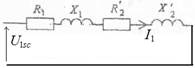
As at experimental short circuit the supply voltage is very lowered, a magnetic flux in a core appears insignificant. Therefore it is possible to neglect losses in a steel. From the equivalent circuit of a transformer it is here possible to eliminate a magnetizing branch, as by a current І 0 in it can be neglected. So as output power at experimental short circuit Р 2 = 0, then a consumed power is spent on payment of losses in the copper of windings (Psc = Δ Pcp):
Δ Pcp = R 1 ∙I 21 nom + R 2 I 22 nom = R 1 ∙I 21 nom + R’ 2 ∙I’ 22 nom = (R 1 +R’ 2)∙ I 21 nom .
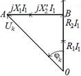
Equivalent circuit of transformer, in accordance with experience of short circuit shown on fig. 1.3. It is corresponded by a vectogram, represented on fig. 1.4. The triangle АОВ on this vectogram is called the triangle of short circuit.
 A hypotenuse АО of this triangle is voltage of short circuit Usc, and its cathetuses ОВ and АВ − accordingly active Ukа = Uk ∙ cos φ k and reactive Ukr = Uk ∙ sin φ k constituents of short Fig. 1.3 circuit voltage.
 Resistances R 1 + R’ 2 = Rk and Х 1 + X’ 2 = Хk are called the parameters of transformer short circuit, as they are determined by data of experience of short circuit:
Rk =Pk / I2 1 nom; Zk = Uk / I 1 nom; Xk = √ (Z 2 k – R 2 k); cos φ k = Pk / (Uk∙I 1 nom).
Usually Z 1 ≈ Z '2. Accordingly R 1 ≈ R’ 2 = Rk /2; X 1 = Fig. 1.4 Х '2= Xk /2.
Dependence of voltage at the terminals of secondary winding on the load current U 2 = f (I 2) at U 1 = const and соs φ2 = const is called external transformer characteristic. Arithmetic difference between secondary voltages of transformer at idling U 20 and at the nominal load current І 2 = І 2 nom at U 1 = U 1 nom and f = const is called the change of transformer voltage and is determined by a formula:
Δ u % = (U 20 – U 2 nom)∙100% / U 20 = (U 1 nom – U’ 2 nom) ∙100% / U 1 nom.
A change of voltage (voltage drop) is important operating characteristic of transformer.
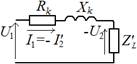 Current in a magnetizing branch ab of equivalent circuit of transformer (see fig. 1.2) equals to the current of short circuit of transformer І 0, which, even at nominal voltage U 1 nom does not exceed 10% of nominal current I 1 nom . It allows in many cases (with the aim of simplification of analysis) and at U 1 = U 1 nom approximately to accept І 0 ≈ 0, that, as well as at experience of short circuit, is equivalent to absence (to breaking) of magnetizing branch ab in the equivalent circuit. According to it the equivalent circuit is called simplified. It is represented on fig. 1.5. In accordance with this circuit, a transformer can be considered equivalent to resistance Zk = √(R 2 k + X 2 k), which is the impedance of Fig. 1.5 transformer short circuit.
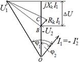 A vector diagram which is built for this circuit at the active-inductive load is represented on fig. 1.6.
This diagram allows to get a close formula for determination of voltage change at the different loading of transformer: ΔU % ≈ kL (Uka % cos φ2 + Ukr % sin φ2), (1.2) where kL = I’ 2 /I’ 2 nom ≈ I 1 /I 1 nom − load factor. As evidently from a formula (1.2) the voltage change depends on the load character. At the active (cos φ2 = 1) and active- Fig. 1.6 inductive (φ2 > 0) load a secondary voltage of transformer drops (Δ U > 0), and in case of the active-capacitive load (φ2 < 0) at enough large phase-shift it increases (Δ U < 0).
A formula for determination of secondary voltage looks like:
U’ 2 ≈ U 1 – ΔU = U 1[1 − kL (Uka cos φ2 + Ukr sin φ2)]
 External transformer characteristics at different character of load, which is determined by an angle φ represented on fig. 1.7. Within the limits of change of transformer load factor kL from a zero up to unit the external characteristics of transformer are almost linear.
At the arbitrary load an efficiency η of transformer equals to: Fig. 1.7
η = P 2 ∙ 100% / P 1 = kL ∙P 2 nom∙ 100% / (kL ∙P 2 nom + P 0 + k 2 L ∙Pk)
and reaches a maximum at kL = √(P 0 / P k), when losses in a copper equal losses in steel (Р 0 = k 2 L ∙Pk).