2015-08-13
 303
3031. To familiarize with the design of the investigated transformer and equipment of the laboratory setting. To write down technical data of measuring devices to protocol.
To assemble a plant for research of transformer by a chart, represented on fig. 1.8.
2. To research open circuit mode; it is needed for this purpose
to turn off by the switch S 1 a load resistance ZL. Setting by means of autotransformer the least of possible voltages, to plug a transformer in a network. Fluently increasing voltage, to take off the readings of devices at the next values of voltage:
0,25 U 1 nom; 0,5 U 1 nom; 0,75 U 1 nom; U 1 nom; 1,2 U 1 nom.
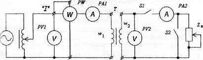
Fig. 1.8
To bring the results of measuring and calculation data to the table. 1.1
Table 1. 1
| Measuring | Calculation | ||||||||
| U 1, V | I 0 А | U 20 V | P 0 W | cosφ 0 | k | Zm, Ω | Xm, Ω | Rm Ω | I 0/ I 1 nom |
3. To research experience of short circuit, for what it is needed at the switched off transformer to include in a chart (fig. 1.8) ammeters with the limit of measuring, which equals to 1,5∙ Inom. To change the limit of measuring to the wattmeter to the necessary limits. To short out secondary winding, closing switches S 1 and S 2. Before powering on the transformer to reduce source voltage up to the zero.
Plugging a transformer in a network, increasing the supply voltage consistently to set the following values of current: 0,1 Inom; 0,25 Inom; 0,5 Inom; 0,75 Inom; Inom;1,2 Inom.
To bring the results of measuring and calculations to the table. 1.2
4. To research transformer in an operating duty at the active, inductive and capacitive load.
At dead source of feed to connect active load resistance to transformer. For this purpose to close the switch S 1 and turn off S 2 (fig. 1.8).
Table 1.2
| Measuring | Calculation | ||||||||
| U 1, V | I 1, А | P 1 W | I 2 А | kL = I 1 / I 1 nom | U 1 = U 1 /U 1 nom | cosφk | Rk,Ω | Zk Ω | Xk Ω |
Before powering on the transformer its voltage must be minimum possible, and load resistance − maximal.
To increase the supply voltage up to the rated value U 1 = U 1 nom . Diminishing resistance of load, consistently to set the next values of current І 2: 0; 0,25 I 2 nom; 0,5 I 2 nom; 0,75 I 2 nom; I 2 nom;1,2 I 2 nom. Primary voltage here to support nominal U 1 nom .
Like to research transformer at inductive and capacitive character of load.
To bring the results of measuring and calculations to the table. 1.3.
Table 1.3
| Measuring | Calculation | |||||||
| I 1, A | P 1, W | U 2. V | I 2, A | cosφ 2 | kL = I 1 / I 1 nom | P 2, W | η, % | Δ U |