2015-08-21
 343
343
Consider the equivalent circuit
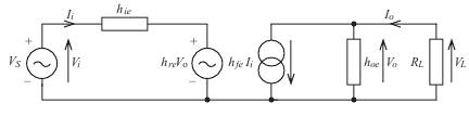
The output is terminated on load R L, which has a value of 1 kΩ. Given the following h parameters, calculate the overall voltage gain from source to load (i.e. V L/ V S).
h ie = 1000Ω, h re = 2 ´ 10–4, h fe = 200, h oe = 10–4 S
Note that in this example V S = V i and V L = V o so that V L/ V S = V o/ V i.
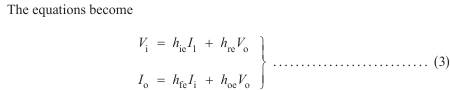
The problem is essentially one of solving the pair of simultaneous equations
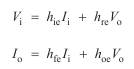
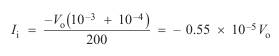
The snag is we have four unknowns. But I o can readily be expressed in terms
of V o and R L.

Remember that the current I o is flowing into the circuit but, according to the
assumed polarity of V o, the upper end of R L is shown as being positive.
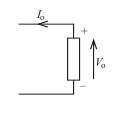
In other words, the assumed directions of I o and V o contradict each other. Hence the need for the minus sign. This is a point to watch in all circuits where assumptions
have arbitrarily been made about polarities and current directions.
Thus, I o = – V o/1000 in our example, which enables a substitution for I o in the
output equation. To save a lot of messy algebra, the numerical values of the h
parameters can also be entered into the output equation.
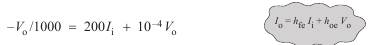
So that
We can now substitute this into the input equation to eliminate I i
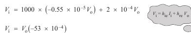
which gives

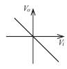
the minus sign in the last equation means is that the output voltage is phase inverted with respect to the input voltage, which is a characteristic of the common emitter amplifier. This is illustrated graphically by the plot of V o against V i shown below.