2015-08-21
 309
309(i) Note that in the equation
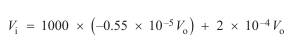
the term 2 ´ 10–4 V o contributes little. In other words, we could ignore the
term due to h re with very little error. This will be true for all the circuits
we shall encounter and we will make this approximation in all subsequent
work. This permits a simplified equivalent circuit
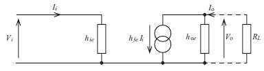
(ii) Any load connected to the output of the common emitter circuit will
appear in parallel to h oe. This will include the collector resistor R c as well
as any other external load connected. We can, if we wish, represent all
such loads by the single equivalent load R ¢L as
(iii) In many applications the transistor's output resistance is very much
greater than the load, i.e. 1/ h oe >> R ¢L. Under such conditions, h oe can
also be omitted from the equivalent circuit and an even simpler model
could be drawn as
(iv) In practice, all the parameters will vary with supply voltage, frequency,
collector current and temperature. For our purposes, though, we will not
worry about such variations and in any given application assume the
parameters to be constant.
Let’s consider the next circuit:
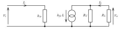
FIGURE upward shows a simplified h parameter equivalent circuit of a common
emitter amplifier. Determine:
(i) the voltage gain V o/ V i
(ii) the current gain I L/ I i
(iii) the power gain P o/ P i
Take h ie = 1500 Ω and h fe = 200. R c = 4.7 kΩ, R L = 2.2 kΩ
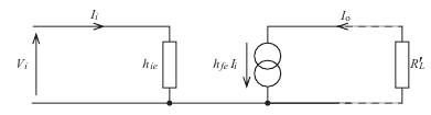
The two resistors on the output can be represented by the single resistor R ¢L
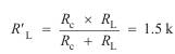 Ω
Ω
The circuit reduces to that shown
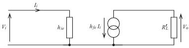
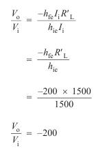
for which we can write
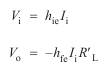
This will yield the voltage gain as