2015-08-21
 537
5373.1 Calculation of ED with load-lifting mechanism. All computations are to be presented accordingly to international system of units. Sequence of calculations is following.
3.1.1. The value of static power (17-19) accordingly to rated load of a motor is defined by the next formula
 (3.1)
(3.1)
Рs – static power of a drive, kWt;
V – the speed of load lifting (appendix 1), m/s;
g - free-falling velocity, which is equal to 9.8 m/ s2;
η – efficiency of load-lifting mechanism.
Efficiency of load-lifting mechanism includes reducer efficiency and drum efficiency. It is approximately equal to 0.85-0.9
3.1.2 By initial data (appendix 1) by calculated power Ps from appendix B the driving EM is choosing.
3.1.3 Determination of load static moment Ms, N·m:
 (3.2)
(3.2)
where ωr – is a rated speed of chosen motor, rad/s;
Ps – is a static power of the motor according to a rated load, kWt;
 (3.3)
(3.3)
where n – is a frequency of rotation of chosen motor, rot/min.
3.1.4 For given values of linear lifting speed V, acceleration a and lifting height H we can calculate the operation time and passed path in the separate areas: run, constant movement and ED braking.

 (3.4)
(3.4)

 (3.5)
(3.5)
where t1, t2, h1, h2 – are the time [s] and path [M] of run and braking respectively;
а – admissible acceleration (deceleration), m/s; (for simplification let us take admissible acceleration of ED run numerically equals to admissible deceleration at ED braking);
hу, tу- the path and the time of constant movement respectively.
 (3.6)
(3.6)
where Tc – is a cycle time;
tо – break time between regular liftings, [s].
3.1.5 To construct the speed diagram V (t) by a data of 3.1.4.
3.1.6 Determination of switching on real duration ПВд of ED.
 (3.7)
(3.7)
3.1.7 Determination of induced moment of inertia Iind (kg/ m2)
 (3.8)
(3.8)
where Іm – inertia moment of ED movable parts, kg/ m2;
Ir – inertia moment of reducer, kg/ m2; Iδ – inertia moment of a drum, kg/ m2;
іР - transmission ratio of reducer.
 For AC motor (appendix 2)
(3.9)
where GD2 – flywheel moment, kg/ m2.
At absence of data about reducer and drum it should be taken
 (3.10)
3.1.8 Dynamic moments Mdyn r and Mdyn br at run and braking
respectively
 (3.11)
 (3.12)
3.1.9 Average starting moment (M1=Mav start) and average stopping moment (Mav stop) can be defined by the formulas
 (3.13)
 (3.14)
3.1.10 Load diagram is constructed by 3.1.3 – 3.1.9 data. Example of a diagram is shown on a figure 3.1
3.1.11 The value of motor equivalent moment Me is determined by the next formulas:
 (3.15)
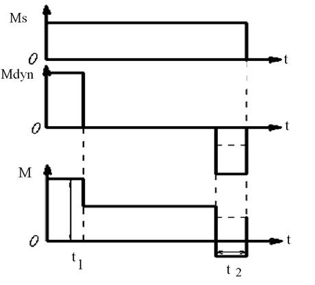


 Figure 3.1 – Load diagram
 (3.16)
where Мі, t1 – are the moment (N  m) and duration (s) of load diagram area;
β – is a factor, allowing the frequency of ED switching on
Nsw.
 (3.17)
At Nsw < 100 factor  ; at Nsw > 100 factor β is decreased from 0.8 to 0.6 (Nsw > 500).
In the next calculations we will use the biggest value of Me.
3.1.12 Determination of operating equivalent moment
 (3.18)
where ПВд is calculated in 3.1.6; ПВпасп – in the appendix Б.
3.1.13 By obtained values of operating equivalent moment we can determine equivalent power of the motor (kWt).
 (3.19)
3.1.14 Checking of chosen motor (3.1.2) by the heating. If Рrat ≥ Реq then the motor by the heating is chosen correct. If Рeq ≥ Рrat, then it is needed to choose another one with the nearest more high power and speed and after those repeat the calculations by 3.1.7.-3.1.14.
3.1.15 Checking of chosen motor by overloading ability is realized by comparison of maximal allowable moment of the motor Мmах (appendix Б) with the maximum moment М1 of load diagram. The next proportion should be performed:
 (3.20)
At the observance of this proportion the motor provide the given acceleration at run area; and if such a proportion is not executed, it is required to choose another motor with the high power high Мmах.
3.1.16 Calculation of natural mechanical characteristic of asynchronous motor with phase-wound rotor. It is needed to define the rated moment of the motor, using ratings (appendix Б).
 (3.21)
where Рrat – is the rated power of the motor (kWt).
 (3.22)
where ω – is a rated angular speed (rad/s).
Overload ability of the motor λ:
 (3.23)
where  - is the maximum torque of the motor (Hm)
Rated sliding
 (3.24)
where ω0 – synchronous angular speed (rad/s), that equals
 (3.25)
where р - is a number of poles pairs
Poles number corresponds to lust digit in reference designation of asynchronous motor type. For example, motor МТН 612-10 has 10 poles, i. e. p=5, motor МТН 112-6 has 6 poles, i. e. that the number of pole pairs equals to 3.
Critical sliding
 (3.26)
Calculation of natural mechanical characteristic of asynchronous motor should be performed by simplified formula of mechanical characteristic (Kloss`s formula)
 (3.27)
where М, S - are current values of moment and sliding.
The given value of sliding S determines the current moment value, formula (3.26) and current speed value by formula (3.27)
 (3.28)
Data of M, ω calculations should be written into the table. The natural mechanical characteristic is constructed with the help of calculation data.
Calculation of electromechanical characteristic should be performed in relative units beside with stated below calculations of mechanical characteristic. Synchronous speed ω0 and rated moment Мn should be considered as the base growth
 (3.29)
 (3.30)
 (3.31)
For determination of current values of speed ω and moment M it is should to use the formulas 3.27; 3.28 for sliding (-)1; (-)0,7; (-)Scr;
(-)Scr/2; 0; Sr; Scr; 1; 1,5; 2.
Calculations should be written into the table 3.1. It should to construct electrical characteristic in relative units with the help of calculation data.
Table 3.1 – Data of electromechanical characteristic calculation
| S | ω | ω * | М* | I* |


(-)1
(-) 0,7
.
1,5
3.1.17 Calculation of natural mechanical characteristic of DC motor.
For DC independent excitation motor (ДПС НЗ) the natural mechanical characteristic is constructed by 2 points.
Point of ideal idle rate (with coordinates ω = ωо; М = 0) and a point of rated mode (with coordinates ω = ωн; М = Мr)
Using ratings (appendix Б) it should to determine:
Rated motor resistance
 (3.32)
Efficiency at rated load Рr (kWt) and resistance of armature circuit
 (3.33)
 (3.34)
Speed of ideal idle rate
 (3.35)
Rated moment of a motor
 (3.36)
Natural mechanical characteristic is constructed by obtained coordinates of ideal idle rate point and a point of rated mode.
By the point of ideal idle rate (with coordinates ω=ω0; M=0)
and point of short-circuit (with coordinates ω =0; M=Мsc).
 (3.37)
where Іsc – short-circuit current [А]
 (3.38)
Mechanical characteristic constructed by modes of idle rate and short-circuit should to coincide with characteristic constructed by idle rate and rated modes.
It is required to calculate and construct the natural mechanical (electromechanical) characteristic in relative units. Speed of ideal idle rate ω0 and rated moment should be considered as the base values.
 (3.39)
 (3.40)
(3.41)
Mechanical characteristic should be calculated in relative units and constructed by data of idle rate and rated mode.
3.1.18 Calculations and constructions of artificial characteristics for rheostat mode of motor speed changing. To calculate and construct artificial characteristic with condition М = Мr, motor speed ω =0,5·ωr. It is needed to determine the additional Rad.
 (3.42)
where Sar – is an artificial sliding for ω =0,5·ωr.
R2 – is an active resistance of rotor phase.
 (3.43)
where Е2r, І2r – rotor voltage and current (appendix Б)
 (3.44)
For ДПС НЗ
To calculate and construct the artificial characteristics for для ω = 0,8; 0,7; 0,5; 0,3 ωr
To determine the additional resistance Rд
For example, for ω = 0.5·ωr
 (3.45)

where Rar – is determined by the formula (3.34)
3.1.19 Calculation of rheostat characteristics of asynchronous motor for previously chosen 2-3 values of Rad.
Calculation should be performed with condition that М = Мr. To determine the value of additional resistance Rad by graphical method for placement of regulative characteristics approximately in a zone вc
(fig. 3.2).
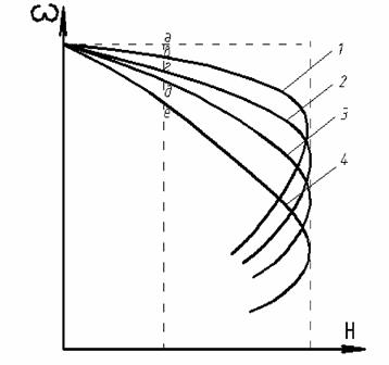
1 – natural-mechanical characteristic;
2,3,4 – regulative mechanical characteristics Figure3.2 – Mechanical characteristic set.
Example: determination of Rad for artificial characteristic 2 (see fig. 3.2)
 (3.47)
 (3.48)
To calculate and construct the artificial characteristics for additional resistances Rad
 (3.49)
where Sad – sliding value from natural mechanical characteristic.
To perform the calculation for the next values
Sad; Sr; Sкcr; S = 1; S = 0,2.
Further calculation is by the formulas 3.16; 3.17.
3.1.20 Calculation and construction of starting diagram of electric drive. Approximate view of starting and braking ED diagrams (for 3 stages of ED) presented on a fig. 3.4.
 17
17
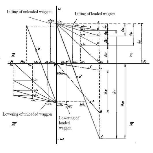
Figure 3.3 – Starting diagram of electric drive
Ms 1,2,3 – are static moments
Four possible operating modes are shown on the figure 3.3: lifting and lowering of loaded waggon, lifting and lowering of empty waggon; braking modes: dynamic brake (ДПС НЗ), counter switching braking mode (ДПС НЗ and asynchronous motor); required geometrical constructions are realized for determination of additional resistances by a graphical method.
In the course project starting diagram (lifting of a loaded waggon) and braking modes are calculated.
Factor J is determined beforehand at the construction of starting diagram by analytic method.