2015-04-17
 1882
1882Tunneling through soft rock requires special consideration as the tunnel’s path may encounter various sorts of hazardous ground conditions such as pockets of methane gas, stretches of water bearing sands, swelling clay, quick sand, silt, mud, gravel, areas of high water inflow, etc. Poor geological formations including sections with severe tectonic pressures as well as stretches of high-pressure water are highly dangerous for driving. Cave-ins are also an ever-present threat while driving in weak rocks due to short stand-up time during which the ground at the point of excavation stands safely by itself. Tunnelling with drill-and-blast method, even with the most up-to-date explosives, is usually unsuitable in soft rock because blasting in shale or limestone is rather difficult to control. These challenges call for clear engineering ideas that can minimize all risks. A special piece of tunneling equipment known as a shield protects workers and provides support (fig.19.1).
The early models of a shield, implemented between 1820 and 1865 by M. Brunel and J. Greathead, were of rectangular or circular shape. Shields had horizontal and vertical bulkheads that made compartments for workers who could dig the entire tunnel face. A Greathead-style shield was followed by the tunnel boring machine (TBM) constructed by J. Robbins.
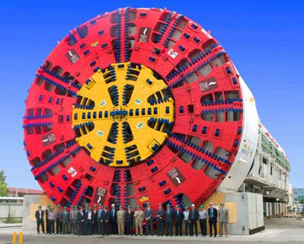 |  |
| a - Shields are powerful sealed steel cylinders for cutting and lining | b - Shields are equipped with mechanisms for ventilation and power supply. |
Figure 19.1 Tunnel Shield Boring Machine (TBM)
Shield technology is very efficient compared to other types of tunneling because modern TBMs do not just cut and protect, they remove excavated material and provide exploratory drilling, ground control and support. They are powerful sealed steel cylinders equipped with mechanisms not only for cutting, gripping and lining, but also for ventilation and power supply.
 | 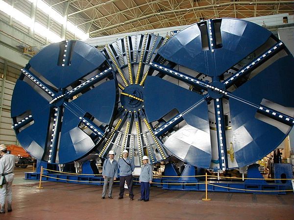 |
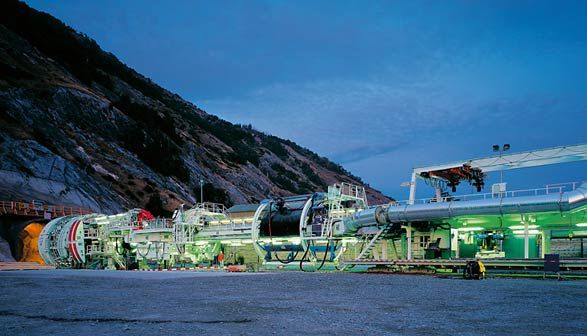
| a - Rotating cutting wheel covered with a combination of milling cutters, disk cutters and steel rotating disks | b - Japanese triple tunnel boring machine |
Figure 19.2 Components of the Rotating Cutting Wheel
TBMs carve a perfectly round opening and support the excavated earth until a permanent lining made out of prefabricated concrete segments is installed. Shield tunneling allows full-face driving without dividing the heading into portions, and the progress rate may be 15-30 m per day or even 300 m/week, as it was during the construction of the Channel Tunnel. No other driving methods can achieve that result.
Present-day TBMs or “moles” are enormous, multimillion-dollar complex systems that match various kinds of the site geology due to the types of cutting devices and their arrangement on the face of the shield (fig. 19.2a).
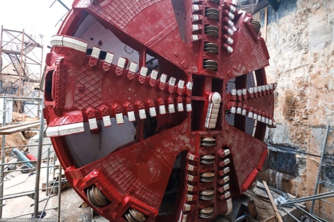
A circular plate is the rotating cutting wheel,called arotating boring head or a cutter head. It is covered with tungsten carbide cutting bits including milling cutters, disk cutters, steel rotating disks ora combination of the three.
The cutting edge grinds the hard rock or slice into soil in the tunnel face by chisel-shaped cutting teeth. Some obstructive inclusions or head-on collision with boulders can damage the cutting edge, and the TBM’s personnel remove or replace the individual segments. In most favorable soil, as it was in the Chunnel, the circular platecan rotate more than 10 revolutions per minute.
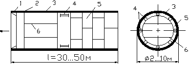
Figure 19.3 Tunnel Shield Structure (конструкция проходческого щита)
1 – Cutting Edge (ножевое кольцо); 2 Non-Rotating Stabilizing Device – (опорное кольцо);
3 – Steel Skin (стальная оболочка); 4 – Shield Jacks (домкраты);
5 – Precast Segments (готовые тюбинги); 6 – Bulkhead (перегородка)
The TBM’s structure also includes a back-up systemconsisting of trailing support decks (fig. 19.1). The back-up system include control rooms for operators, break-time space for workers, conveyors and slurry pipelines for tunnel muck removal, firefighting equipment, electrical support equipment, ventilation and dust removal systems. The rock, excavated by TBMs, passes through spaces in the rotating boring head onto a belt conveyor, which carries it through the shield to the rear of the machine where it drops into muck carrying vehicles for removing it from the tunnel.
The shield diameter may range from one to 10 m and its total length may reach up to 30 or even 50 m (fig. 19.1). Large diameter TBMs allowed the construction of bi-directional rail tunnels. Massive robotic arms, mounted at the rear of some machines, raise lining segments to the final location as soon as the shield has advanced at sufficient distance. To propel the shield forward through rock, the gripper arms extend outward from its sides and push firmly against the tunnel walls. Using hydraulic cylinders, they propel the shield at the predetermined distance, or hold it in place for keeping the cutter head in contact with the tunnel face while cutting it.
The shield diameter may range from one to 10 m and its total length may reach up to 30 or even 50 m (fig. 19.1). Large diameter TBMs allowed the construction of bi-directional rail tunnels. Massive robotic arms, mounted at the rear of some machines, raise lining segments to the final location as soon as the shield has advanced at sufficient distance. To propel the shield forward through rock, the gripper arms extend outward from its sides and push firmly against the tunnel walls. Using hydraulic cylinders, they propel the shield at the predetermined distance, or hold it in place for keeping the cutter head in contact with the tunnel face while cutting it.
Shielded hard rock TBMs work in hard or fractured rock. The Double Shield TBM with two modes of operation is applicable both in stable and unstable ground (fig.19.5a). One operation mode, used in stable ground, allows these TBMs to advance by gripping against the tunnel walls. The other operation mode is for unstable, fractured ground where the TBMs advance by thrust cylinders. They push off against the most recently installed tunnel segments that protect the fragile tunnel walls.
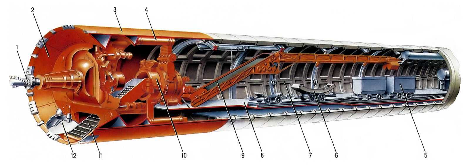 | |
| a - Tunnelling shield with main bearing (щит проходческий со штанговым рабочим органом): 1 – cutting wheel (рабочий орган); 2 – cutting head (ножевая часть щита); 3 – skin (shell) (корпус щита); 4 – shield jack s (домкрат-передвижки); 5 – muck-carrying vehicle (вагонетка); 6 – segment-carrying vehicle (блоковозка); 7 – segmental lining (обделка); 8 – t railing backup system for muck and material transportation, ventilation, power supply, etc. (технологическая платформа); 9 – belt conveyor (ленточный конвейер); 10 – erector (блокоукладчик); 11 – scraper [пластинчатый (скребковый) конвейер]; 12 – muck chamber (погрузочное устройство) | |
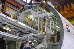 | 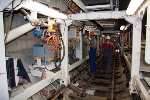 |
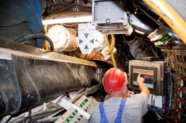
| b – Workers ansembling a TBM in a launching chamber | c – Workers operating a TBM within a tunnel |
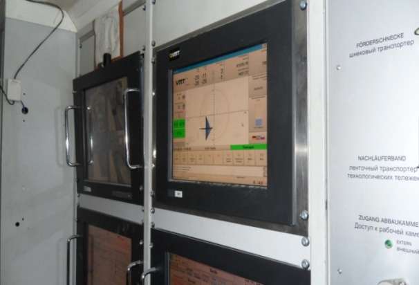 |  |
| d - Devices and instrumentation for TBM operation |
Figure 19.4 TBM Body Structure
The Single Shield TBM (fig.19.5b), that is applicable only in fractured ground, provides three operational modes (open, semi-pressurized and pressurized). These TBMs advance by pushing off against the concrete segments that are already in place and joined.
 |  |
| a - Double Shield TBM – щит “телескоп”, двойной щит | b - Single shield TBM (“единый” щит): 1 - shield; 2 - thrust cylinders; 3 - segmental lining; 4 – cutting head; 5 muck bucket (приёмник породы); 6 - conveyers |
Figure 19.5 Shielded hard rock TBMs
Modern tunneling employs either an open-face type or closed-type machines. The "head" parts of the closed-type machines are "closed" and separated from their rear parts. These machines are known as EPB (earth pressure balanced) and SS (slurry type shield machine). To advance forward both of them are equipped with thrust cylinders that push off against concrete segments.
The EPB type shield machine (fig. 19.6) is suitable in soft ground because it can maintain the balance between earth and the backpressure. This gave it its name. This machine may be applicable for clay soil with less than seven bar of pressure, and is not suitable for hard rock because the excavated soil is difficult to be turned into slurry. To counterbalance the cutting face under soil and water pressures in front of the TBM, the "head" part is equipped with an excavation chamber between the cutting face and bulkhead. Soil or slurry enters the excavation chamber during the boring process. Mud pressure in the excavation chamber stabilizes the cutting face and holds it under soil pressure. The TBM operator keeps the soil pressure at a constant value by automated control system that helps to balance the rates of soil discharging and machine advancing. One or two screw conveyors transport the soil away from the cutting head to the conveyer belt.
 |
| Earth Pressure Balance Machine (щитовой проходческий комплекс с грунтопригрузом): 1 – Cutting head (ножевая часть щита); 2 - Excavation chamber (приёмник породы); 3 – Bulkhead (перегородка); 4 - Thrust cylinders (домкраты); 5 - Screw conveyor (винтовой конвейер); 6 - Segment erector (блокоукладчик); 7 - Segmental lining (обделка) |
Figure 19.6 Earth Pressure Balance Machine
The Slurry Shield (SS) is suitable for soft ground saturated with large amounts of ground water under very high pressure (fig. 19.7a). It can operate below the water level due to the pressurized compartment at its front end. The SS has slurry feed line and removal equipment for pressurizing and circulating slurry. It balances the water pressure by the external pressurized slurry that stabilizes the tunnel face ahead of the cutter head. If the soil surface is not workable enough the bentonite slurry is pumped into the cutting head where it is mixed with the excavated soil that is transported by fluid conveyance done by circulating mixed slurry. The mixed slurry is pumped out onto the surface through slurry tubes. Then it is separated again into the bentonite and dirt at slurry treatment plants (fig. 19.7b). Next, it is recycled back into newly excavated soil in the tunnel face. The room behind the pressurized compartment, where the operator works, has normal air pressure and a totally enclosed working environment.
Open face TBMs are used either in hard rock or in soft ground with low water inflows or if the tunnel face is able to stand up without support for a short period of time while being excavated. The open-type machines do not put concrete lining. The workers install ring beams and steel straps, spray shotcrete or secure rock bolts and wire mesh to hold up the rock.
 | 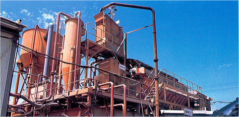 |
| a - SS type machine [щитовой проходческий комплекс с гидропригрузом (с гидротранспортом породы)]: 1 – Cutting head; 2 - Excavation chamber (герметичная призабойная зона); 3 – Bulkhead; 4 - Slurry feed line (подача гидропригруза); 5 - Air cushion; 6 - Wall; 7 - Segmental lining; 8 - Segment erector | b - Slurry treatment plant |
Figure 19. 7 Technological Process by the Slurry Shield Complex
Though shields require considerable time for setting-up, they are easily operated and ensure an accurate breakthrough when they dig toward each other from opposite tunnel ends in hostile ground environment. The TBM operator uses control systems to avoid any wobble and eccentric rotation of the cutter head because the diameters of the tunnel and the cutting head must be equal in sizes. Driving a smooth curve with a shield requires great skill and experience. It is costly or even impossible to withdraw shields from the heading. Each of the two opposite shields may dig a short spur to steer them away from the path of the tunnel for permanent sealing.
Shield tunneling has many advantages; however, it has some disadvantages as well. First, there are non-mechanical shields and the workers have to use hand tools for loading the muck or placing the lining segments. Second, only small shields are assembled in the shop and. They are shipped to the job site in one piece. Most shields are assembled in situ, at the tunnel portal or at the bottom of the launching shaft. Assembling, starting and dismounting the shield in situ require a special mounting platform, and are very expensive and labour consuming operations.
Civil engineers consider shields to be a promising area of improvement. They have devised multiple-headed TBMs for simultaneous boring of two or three parallel tunnels (fig.19.1b). Recently built shields are able to turn a corner up to 90° during a tunnel boring operation. The necessity for drilling core samples and boring probe headings ahead of tunnel face has been also reduced due to a virtual CAT scanning that is generated by sound waves which are transmitted through the earth. The trend in TBM design is towards remote control systems. It will improve workers’ safety and reduce the working time in the underground space.