2015-08-13
 322
3221. To familiarize with the generator of parallel excitation, equipment, measuring devices and write down their technical characteristics in a table 2.1:
Table 2.1
| Name of device | Conditional denotation on a chart | Measuring system | Class of exactness | Borders of measuring | Cost of division of scale |
To write down the nominal parameters of the under test generator in a table 2.2:
Table 2.2
| Nominal parameters of generator | ||||||||||
| Preset parameter | Calculated and observable parameters | |||||||||
| Uno, V | Pnom W | nnom, rpm | Inom, A | Rarm, Ω | Iexc, nom, A | Iarm,no, A | Rexc,nom, Ω | Enom, V | η | ksat |
2. To calculate the value of nominal load current of generator I nom under the formula Inom = Pnom/Unom and write down it in a table 2.2.
3. To measure a resistance of armature circuit of immobile rotor Rarm by the method of ammeter and voltmeter. Results write down in a table 2.2.
4. To assemble a plant for research of DC generator G with the parallel excitation winding EW according to a chart on a fig. 2.1,
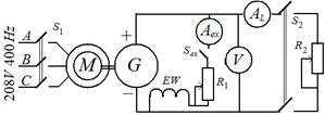
Fig. 2.1
where M is a DC motor with the centrifugal stabilizator of speed;
− EW, S 1, resistor R 1, rheostat R 2, Aex is an excitation winding, resistor, switch and ammeter of the excitation circuit;
− V, AL, S 2, R 2 is a voltmeter, ammeter, switch and rheostat of load circuit;
5. To define the value of nominal excitation current Iexc, nom by means of experiment, for what to switch on a Sex, turn off the switch S 2 and, setting maximal resistances of resistor R 1 and rheostat R 2, to start up a motor M by means of switch S 1. After selfexcitation of generator to switch on S 2 and by means of resistor R 1 and rheostat of R 2 to set the basic values of generator voltage Unom and load current IL. To define the excitation current Iexc, nom with the help of ammeter.
To define basic values: armature current Iarm, nom, resistances of excitation circuit Rexc,nom, EMF Enom and efficiency factor η nom under formulas:
Iarm, nom = IL − Iexc, nom; Rexc, nom = Unom/ Iexc, nom; Enom = Unom + Rarm Iarm, nom; ηnom = 1– RarmI2arm,nom / [(0,5÷0,7) Unom Iarm, nom ].
To write down the results of measuring and calculations in a table. 2.2.
To remove load and excitation of generator, putting the resistor R 1 and rheostat R 2, in previous position turning off the switches S 2 and S ex.
6.To characterize a characteristic of open circuit of generator E = f (Iexc) at Ω = Ω nom.
To measure voltage of generator, which corresponds EMF, excited by a resigual magnetic flux. Smoothly increasing the excitation current, to characterize the rising branch of o.c. characteristic. After achievement of maximal voltage of Umax = 1,2 Unom, which corresponds to EMF Emax, smoothly diminishing the excitation current, to characterize the descending branch E = f (Iexc).
Attention! To change the value of excitation current only one-way.
To write down data of measuring in a table. 2.3.
Table 2.3
| Experimental characteristic | Averaged characteristic | ||||||
| Rising branch | Descending branch | ||||||
| ↑ Iexc, A | U, V | E, V | ↓ Iexc, A | U, V | E, V | Iexc, A | E, V |
To calculate EMF of armature winding under the formula of E = U + RarmIexc and average out the calculated values of EMF of both branches at the chosen values of excitation current. To write down results in a table. 2. Under data of table. 2 to build averaged characteristic of o.c. E = f (Iexc) and by it to define the saturation coefficient of magnetic chain of machine ksat. To write down results in a table. 1.
7.To characterize an external characteristic of generator U = f (I) in such sequence:
а) to set the nominal mode of operations of generator;
b) to unload a generator to the o.c. mode;
с) to load a generator to the critical point of characteristic;
d) to load a generator to the s.c. mode.
For this purpose to switch on Sex, after selfexcitation of generator switch on S 2 and by means of resistor R 1 and rheostat R 2 to set the basic values of generator voltage U and load current I. Further, not changing position of regulator handle of resistor R 1, gradually to increase resistance of rheostat R 2 to the maximal value, taking data of measuring devices. Whereupon to turn off S 2 and write down the data of measuring devices for the plotting of initial point of characteristic which corresponds to o.c. characteristic of generator.
Because after achievement of critical current Icr the generator voltage arbitrarily falls to the zero, then should beforehand to define by experimental path the approximate value of critical current, and then to continue to characterize a characteristic.
After it to switch on S 2 and set the nominal load current IL. Then, gradually to diminish resistance of rheostat R 2 to the value at which the load current will attain a critical value Icr, taking data of measuring devices. After achievement by the current I of critical value Icr to decrease resistance of rheostat R 2 to the zero and measure the current of short circuit Isc.
After measuring to transfer a generator in the o.c. mode, for what to turn off the switch S 2 and increase resistance of rheostat R 2 to the maximal value.
To write down the results of measuring in a table. 2.4.
Table 2.4
| Measuring | Calculations | ||||||
| U, V | I, A | Iexc, A | Icr, A | Isc, A | ΔU, % | Icr/Inom | Isc/Inom |
To calculate the change of generator voltage in percents of nominal voltage Δ U, % under the formula Δ U, % = (Uoc − Unom)∙100/ Unom, and also ratios of currents Icr/Inom, Isc/Inom.
To write down the results of calculations in a table 3. From data of table 3 to build external characteristic of generator U = f (I).
8. To characterize a regulation characteristic Iexc = f (I) at U = Unom. For this purpose at o.c. of generator by means of resistor R 1 to set nominal voltage Unom and measure the excitation current. After it to switch on S 2 and gradually diminishing resistance of rheostat R 2 and keeping up a generator voltage unchanging by means of resistor R 1, to take data of measuring devices. The load current it is here necessary to increase until generator voltage can be supported by unchanging.
To write down the results of measuring in a table. 2.5.
Table. 2.5
| U = Unom, V | I, A | Iexc, A |
Under data of table. 2.5 build regulation characteristic of generator U = f (I).