2015-08-21
 771
7711. Block diagram of the digital transmission system (DTS) including error-control code encoder and decoder is described in [1, p. 5].
2. For explanations of term “coding gain” section 8 [1] and expression (1) can be used
D =  /
/  or D [dB] = [dB] – [dB]. (1)
were is signal-to-noise ratio on the demodulator input, providing the given bit error probability р all at the demodulator output in transmission system without error-control coding;
 is signal-to-noise ratio on the demodulator input, providing the given bit error probability р all at the decoder output in transmission system with error-control coding.
Choice of error-control code. From three code parameters n, k and qc two can be chosen independently, and the third is expected on Hamming’s lower bound for number of additional symbols (n – k), formula (2):
2 n – k – 1 ³  . (2)
. (2)
Usually independent parameters are n and qc. For their choice it is necessary to take into account:
- with increasing of qc theCG increases too, but the complication of decoder increases sharply;
- with increasing of n theCG increases, but for large n (about 100) growth of CG is slowed, and then it can reduce (fig. 2).
Therefore at choosing of code parameters it is necessary to enumerate the possibilities, by a successive transition from less difficult codes to more difficult. To facilitate the choice of code parameters, on fig. 2 dependences of CG on n for the different values qc are resulted. For the values рd, which are not resulted in a fig. 2, CG can be estimated approximately, considering that CG linearly depends on lg рd.
For given CG and allowable symbol error probability at the decoder output рd,using fig. 2 the order of corrected errors qc and code length n can be determined. Both of these code parameters have to be the minimum possible. At increasing of qc thecomplication of decoder increases faster, than at increasing of n, then, mainly, value qc must be minimum. After n and qc determination a value k can be calculated from relation (2).
For perfect codes inequality (2) passes to equality and the number of the redundant symbols n - k is minimized for the fixed values n and qc. The cyclic Bose-Chaudhuri-Hocquenghem (BCH) codes become widespread. The parameters of BCH codes are close to the perfect code and at the same time require to rather simple scheme of encoder and decoder. Parameters of the BCH codes are bound by relations:
k = n – mq c, (3)
where m – the least integer value, which satisfy inequality-equality:
m ³ log2 (n + 1). (4)
Checking the result. Chosen code parameters n, k and qc it is necessary to consider as tentative, and the correctness of code choice must be confirmed by calculations. For this purpose it is necessary to calculate:
- signal-to-noise ratio at the demodulator input in transmission system with error-control coding  = , defined by formula (1);
– symbol error probability at the demodulator output p by the formula for given modulation type, substituting h =  ;
;
– probability of error decoding of code word P e don formulas (5) - (7), in sum in formula (5) it is enough to take into account only first element.
– symbol error probability at the decoder output pd on a formula (8).
In the case of decoding with errors correction the probability of error decoding of code word P e.d is determined from a condition, that the number of errors in code word at the decoder input q exceeds order of the corrected errors q c:
 , (5)
, (5)
where Р (q) =  pq (1 – p) n – q (6)
– probability of error of order q;
 (7)
(7)
– binomial coefficient;
р –error probability of binary symbol at the decoder input. If р << 1, then in the series (5) sufficient to take into account only the first member, in the formula (6) it is possible to ignore a factor
(1 – p) n – q .
In these formulas it is necessary to substitute h = (because of symbol duration decreasing at addition of redundant symbols in encoder and proper decreasing of elementary signal energy at the demodulator input).
For a transition from probability P e.d. to binary symbol error probability at the decoder output рd it is enough to take into account principle of errors correction in decoder: a decoder replaces the forbidden code word on nearest permitted. Therefore, if a number of errors in code word is q > q c, but q £ d min, then a result of decoding will contain d min errors (d min – code distance). As more high error orders are improbable, it is possible to consider that the erroneous decoded code word contains d min error symbols. In error-control codes code distance d min ³ 2 q c + 1 (typically d min = 2 q c + 1). As at the erroneous decoding of code word the 2 q c + 1 symbols from n are erroneous, then transition from Р e d to р d can be executed on formula:
р d = Р e d (2 q c + 1) / n. (8)
 (9)
(9)
Note that in a fig. 2 the values n are indicated for equality n = 2 m – 1. At calculations code length n can take on any intermediate value.
If value р d £ р all, then the chosen code provides necessary CG, but if р d > р all, then the chosen code doesn’t provide necessary CG. With the purpose of minimization of values q c and n it is necessary to make calculations for 3-5 codes. The calculations results write in the Table 1.
Table 1 – Results of calculations for the code choice
| code (n, k) | q c | k / n | p | Р e d | р d |
The better code has minimum possible qc and the least value n at which set CG is provided. In this case the codec complication is minimal.
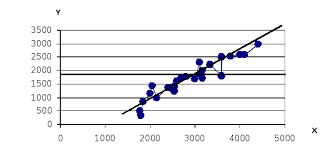
3. After the choice of code it is necessary to calculate dependence, characterizing noise immunity in a communication channel with error-control code. For this purpose change  in such limits, that the value рd took on values from 10–2 to the value which is a few less than р all, build dependence р d = f 2 () as resulted in a fig. 1. On this dependence determine a necessary signal-to-noise ratio at the demodulator input
  , at which allowable symbol error probability is provided at the decoder output, i.e. р d = р all. Using values and , determine CG on a formula (1) and compare it with necessary CG.
4. Minimum possible signal bandwidth is determined by the Nyquist limit [2]: for МASK, М PSK, М DPSK, М APSK and М QAM
Fs = 1/(T s log2 M), (10)
and for М FSK
Fs = M /(T s log2 M), (11)
where Т s – binary symbol duration at the modulator input;
М – number of elementary signals.
In transmission system without error-control coding, value Т sequals to binary symbolduration Тb at the transmission system input. If the noise immunity encoding is used, then Т s= Т b k / n, where n and k – error-control code parameters.
5, 6. Formulas for calculation of efficiency coefficients: (12.1) – (12.3) in [1, p. 53].
The continuous communication channel capacity is determined by Shannon formula [3, p. 28]. Communication channel bandwidth F c, in this formula, equal to the modulated signal spectrum bandwidth Fs.
For determination of ratio Ps / N 0 at the communication channel output it is necessary to use next formula:
 . (12)
The calculations results write in the Table 2.
Table 2 – Parameters of the compared transmission methods
| Transmission method | Parameters | ||||||
| R, kbit/s | F c, kHz | Ps / N 0, Hz | С, kbit/s | h | b | g | |
| Transmission without error-control coding | |||||||
| Transmission with error-control coding |
7. On the graph with Shannon limit b = f (g) [1, p. 54, 56] point values of b and g in logarithmic units: 10 lg b and 10 lg g accordingly.
Comparison of the considered variants of transmission executed separately on coefficients b and g. It is necessary to specify the methods of energy and frequency efficiencies increasing.