| Steel grade | Blank diameter, mm(max) | Brinell hardness, | s ul | s y | Heat treatment |
| MPa | |||||
| 0.45C | 170 to 217 BHN | Normalizing | |||
| 0.45C | 192 to 240 BHN | Martempering | |||
| 0.40C-Cr | 230 to 260 BHN | Martempering | |||
| 0.40C-Cr | 260 to 280 BHN | Martempering | |||
| 0.40C-Cr-Ni | 230 to 300 BHN | Martempering | |||
| 0.35C-Cr-Mo | >240 BHN | Martempering | |||
| 0.40C-Cr-Ni-Mo quality | >302 BHN | Martempering |
For example, let us choose Steel 0.4C-Cr (40X) heat treated by martempering to hardness ranged from 230 to 260 BHN, s ul = 850 MPa, s y = 550 MPa.
10.2. Analyze a shaft for static strength.
10.2.1. Plot the analytical model of a shaft and apply all acting forces (Fig. 10.1). In this case a shaft is considered as a beam mounted on two supports, in particular on one immovable hinge support and one movable hinge support.
Let us analyze forces which may act on a shaft.
It is necessary to remember that in the engagement of straight spur gears turning force Ft and radial force Fr develop (radial force is always directed to the centre of rotation of the gear). In the engagement of helical gears, bevel gears and worm gearing besides turning and radial forces axial force Fa develops. This force is parallel to the shaft axis. Values of mentioned above forces were found during of analysis corresponding gear drives for strength.
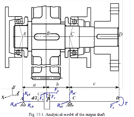 On the cantilever portion of the shaft either a pulley or a sprocket or a half coupling may be mounted.
If a pulley or sprocket is installed on the shaft a force acting to the shaft from the side of the element is directed along the centre line of the mechanical drive. The value of this force was determined during analysis of the corresponding mechanical drive.
If a half coupling is installed on the shaft the first loads the shaft by the torque. Additionally, because of misalignment of shafts joined by the coupling the latter exerts upon the shaft an additional force Fc. This force may be directed to any side (with respect to turning force Ft). But for analytical models we will consider the worst case when this force is directed opposite to Ft. In this case the shaft deformations are maximum.
The value of this force is determined in the following way:
- for single stage speed reducers  ;
;
- for double stage speed reducers  ,
,
where T is the torque at the shaft in N·m.
10.2.2. Plot the analytical model of the shaft in the vertical plane and transfer all forces to the shaft (Fig. 10.2). It is necessary to note that according to the theoretical mechanics as a result of transferring parallel forces to any point the additional moment develops. In our case it is axial force Fa that is parallel to the shaft axis. That is why the additional moment is
 ,
,
where dg is the pitch circle diameter of the gear.
So 

10.2.3. Determine vertical support reacting RyA and RyC. For this purpose we should consider the equilibrium of the beam and set up equations of moments with respect to points A and C:
 ,
,  .
.


For checking we set up equation of forces that act in the vertical plane of the shaft. The sum of these forces should give zero ( ).
).

10.2.4. Plot the diagram of bending moments in the vertical plane ( ) (Fig. 10.2).


10.2.5. Plot the analytical model of the shaft in the horizontal plane and transfer all forces to the shaft (Fig. 10.2). In this case as a result of parallel transferring force Ft the torque T develops
 .
.
10.2.6. Determine horizontal support reacting forces RXA and RXC. For this purpose we should set up equations of moments with respect to points A and C:
 ,
,  .
.


For checking we find the sum of all forces that acts in the horizontal plane of the shaft. This sum should be equal to zero ( ).
).

10.2.7. Plot the diagram of bending moments in the horizontal plane ( ) (Fig. 10.2).
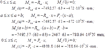
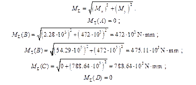
10.2.8. Plot the diagram of total bending moments (Fig. 10.2) taking into account that
10.2.9. Plot the twisting moment diagram (Fig. 10.2).
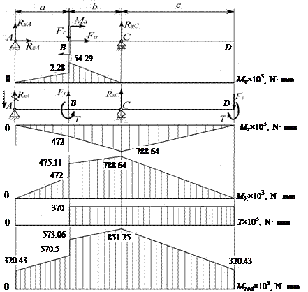 Fig. 10.2. Diagrams of moments for the shaft analytical model
10.2.10. Plot the reduced moments (Fig. 10.2) diagram taking into account that Мred
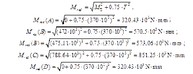
10.2.11. For the critical section of the shaft (where the reduced moment is maximum) we check the shaft for static strength
 ,
,  ,
,

where d is the diameter of the shaft at the critical section; [σ b ] is the allowable bending stress. For steels [σ b ] = 120 MPa.
Condition is satisfied.
If σ b > [σ b ] we must increase the diameter of the shaft at the critical section.
10.3. Analyze the shaft for fatigue strength.
10.3.1. Determine the limit of endurance in bending and in torsion for the shaft material:
for carbon steels: s-1 = 0.43·s ul, 
for alloy steels: s-1 = 0.35·s ul + 120,
t-1 = (0.2…0.3)·s ul, 
where s ul is the ultimate strength of the material (table 10.1).
10.3.2. Determine peak magnitudes of bending and torsion stresses (s p, τ p) at the critical sections of the shaft.
Critical section is a section where the total moment MΣ is maximum. It may be a section where a gear or a bearing is located.
 ,
,  ,
,
where d is the diameter of the shaft at the critical section.
10.3.3. Determine mean components of the bending and torsion stresses (s m, τ m).
If axial force Fa <1000 N we assume s m = 0 and τ m = τ p .
Otherwise
 , τ m = τ p ..
In our case Fa = 346.7 N < 1000 N, so s m = 0 and τ m = τ p = 5.56 MPa.
10.3.4. Determine factors ys and yt of mean stress components
- for carbon steels ys = 0.1 and yt = 0.05;
- for alloy steels ys = 0.15 and yt = 0.1.
In our case ys = 0.15 and yt = 0.1.
10.3.5. Determine effective stress concentration factors Ks and Kτ. For this purpose we use table 10.2.
If the critical section of the shaft is a section where a bearing is mounted we will use as stress concentrator interference fit. If a gear is installed at the critical section a keyed portion is considered as the stress concentrator.
 2015-08-21
 538
538


