2015-08-21
 341
341Over this range the coupling capacitors are assumed to be behaving themselves
and may be regarded as having negligible impedance (compared to the
resistances in the circuit). They can, therefore, be ignored in any calculation.
Conversely, the box's internal capacitances, which are low in value, will have a
very high impedance. However, they appear in parallel across the load and
thus can also be neglected from any calculations.
Over the mid-frequency range, then, the behavior of the circuit is assumed to
be due entirely to resistive components. A suitable equivalent circuit is shown
below.
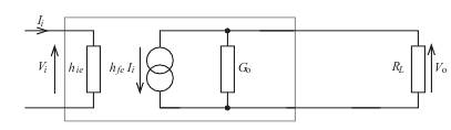
The current gain is given by
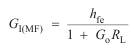
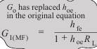
The only thing novel is the subscript 'MF' used in the symbol for current gain. Shortly, we will be expressing G I as a function of frequency and we need some means of distinguishing between the three frequency ranges over which the amplifier can operate. We will use the subscripts 'MF' for mid-frequency, 'LF' for low frequency and 'HF' for high frequency ranges.
The voltage gain is given by
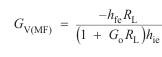
this being simply a factor  times the current gain value.