2015-08-21
 377
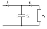
377Above the mid-band range the effect of the coupling capacitors can be ignored
but the capacitance across the load resistance will come into play. At high
frequencies, the equivalent circuit can be drawn as
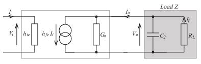
Again, using the approach of representing the total load by Z, we can write
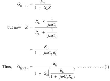
Equation (1) is based on above figure in which I o is the current through Z. But in the case of low and mid-band gains we have defined the gain as  where I o is the current through R L.
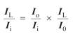
To be consistent on our definitions of current gain, we need to modify
Equation (1) to define the gain as 
This is easily done by using the 'ratio method' for determining the current in one branch of a parallel circuit.
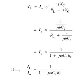
Now we note that
In order to modify the current gain G I(HF) to the ratio  we need to multiply
Equation (1) by the factor 
Our modified current gain thus becomes
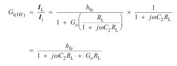
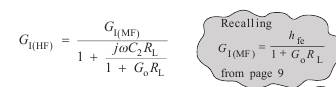
If we now divide the top and bottom lines of this last expression by (1 + G o R L), this will give us an expression for G I(HF) in terms of the mid-band gain.
To tidy things up, we will define w2 as 
Then
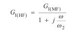
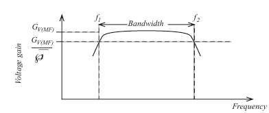
The frequency f2=ω2/2π represents the upper half-power frequency. The
bandwidth of the amplifier is given by f 2 – f 1. This is illustrated in the
frequency response below