2015-08-21
 326
326In the foregoing discussion we have identified the possible causes of reactance
which could limit the frequency performance of our electronic black box.
Imagine, now, that one black box is used to drive another, as shown below
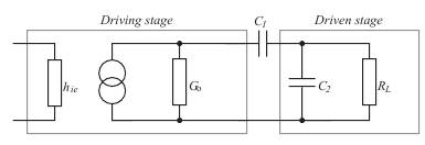
The driving stage is represented in the usual way by an input equivalent circuit,
in this case simply a resistance, and an output equivalent circuit consisting of a
current generator and the output conductance G o. This conductance is due to
the combined effects of the transistor's output conductance, h oe, in parallel with
the collector resistor R c. The driving stage is coupled by C 1 to the driven stage.
Only a modified input equivalent circuit is shown for the output circuit. It
consists of a capacitance C 2 in parallel with a resistance R L.
C 2 and R L represent the total loading of the second stage upon the first. To
predict the frequency behavior of the circuit, all we need do is to express
the current and voltage gains as a function of frequency. It is usually possible to identify three different frequency ranges in which an amplifier can operate. This will enable us to ignore some, or even all, of the capacitive effects within a particular range.
________________________________________________________________________________________