2015-08-21
 405
405Other clutches used on the driving systems protect the machine parts against damage in case of clogging.
The friction slip clutch is like that on standard-transmission cars and is similar to some tractor clutches.
The ratchet slip clutch will let you know when it slips. It has two hubs with sloping teeth that mesh together. They are held together by a heavy coil spring and adjusting nut. When a heavy slug stops a ratchet-protected device, the teeth slip over each other and make a noise. You can adjust the spring tension but your machine is safer if this is not too tight. You can readily identify this clutch by the teeth, the single compression spring, and nut (Fig. 8b).
The auxiliary engine's power is transmitted to the flywheel and cutter head by various methods. In some models the engine has a handy friction clutch that is used to start and stop the entire mechanism. Others tighten V-belts when power is needed from the engine. One make uses a flat belt for power transmission. Some use chains for the first stage of the power drive.
Belts are useful and practical. In the event of clogging, they slip and little harm is done. If chains or gears are used, other safety devices must be provided such as shear pins and slip clutches.
The Cylinder Cutting Mechanism. This consists of a shaft, two or three spiders, two to eight knives, and a shear plate. The spiders are fastened to the shaft and the knives are bolted to the rims of the spiders. The knives can be loosened and adjusted, usually by turning a bolt and locking the bolt with a nut. The knives can be readily removed for sharpening and for changing the cutting length.
The cylinder is at the end of the conveyor apron. Each blade or knife nearly scrapes the edge of a very sharp and hard shear plate. Since each knife is spiral-shaped, the cutting between knife and plate is a shearing action. The shear plate can be changed so that a different edge may be used when one edge dulls – it usually has four cutting edges. The edges must be kept sharp.
The cylinder mechanism has little momentum of its own. Therefore if a slug of material enters, the cylinder may stop and perhaps stall the engine, shear a pin, or slip a clutch.
One manufacturer places the cylinder on end. The lower end is close to the ground and therefore forage need not be elevated very high. The conventional cylinder is 2 or 3 feet from the ground and all material, including corn butts, must be elevated that high – and sometimes this gives trouble. The vertical cylinder, however, requires that all material be funneled to a rather narrow vertical opening. Therefore that machine has vertical cross belts to move wide windrows to the center.
One manufacturer combines the blower mechanism with the knife cutters. The spiral knives are wide and cup-shaped. This wide area propels the cut forage up and through the discharge spout to a trailing wagon.
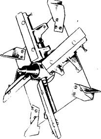
The Flywheel Cutting Mechanism. This consists of a heavy boiler plate (Fig. 9), knife holders and adjustment devices, two to six knives, about four paddles for blowing, and a shear plate.
The boiler plate is fastened to the heavy cross shaft. It must be very well centered and balanced. Four or six sets of knife holders are riveted or welded to the plate. The knives are securely bolted to the holders so that they cannot work loose.
The knives are about 1/2-inch thick and are sharpened on the beveled side. The straight side is usually placed next to the shear plate. The knives are adjusted so that there is just a room for a piece of heavy paper between the knife and plate. This adjustment is important if the flywheel shaft develops end play; you must remove it following instructions from your owner's manual, and adjust it accurately.