2015-08-21
 450
450After designing a shaft construction and determination of sizes of all elements mounted on a shaft it is necessary to find distances between elements which are located on a shaft. For this purpose a sketch layout of a speed reducer should be made. In this case a speed reducer is drawn in one projection (top or front view) to scale 1:1 on profile paper.
Let us consider as an example plotting a sketch layout of single stage spur gear speed reducer.
1. Plot a spur gears taking into account dimensions which were determined during strength analysis and in p.9.3.1 and 9.3.2. We will begin from plotting the centre distance, pitch circle diameters, addendum and dedendum circle diameters of a pinion and a gear. The engagement of gears has to be represented as in Fig. 9.8.
2. Determine disposition of inner walls of a speed reducer. In order to eliminate contact of gears with a wall it is recommended to locate the inner wall by distance 10 mm with respect to a gear hub and by distance 20 mm with respect to gear face end.
3. Determine disposition of bearings. In this case we should take into account that inner surface of a bearing assembly has to be protected from grease washing out. For this purpose grease retaining rings are used (Fig.12.12). The width of these rings is ranged from 10 to 12 mm. That is why bearings are located by distance 10 mm with respect to speed reducer inner wall.
4. Plot bearings for input and output shafts using dimensions from tables 9.3-9.5.
5. Determine disposition of outer walls of a speed reducer. Outer wall is located by distance 0.5∙Bmax, where Bmax is the width of the largest bearing.
6. In a speed reducer bearing assemblies have to be protected by bearing caps from the side of speed reducer outer walls. The width of these caps is ranged from 8 to 12 mm. Let us draw straight lines by distance 10 mm with respect to speed reducer outer walls to determine approximate disposition of bearing caps.
7. Plot lip seals for input and output shafts using dimensions from table 9.6. A seal is located in a bearing cap by distance 3-4 mm with respect to bearing cap face end.
8. Make an arc along input and output shaft axes by distance 20 mm with respect to bearing caps to determine disposition of the first shoulder of a shaft.
9. Lay out length of an element mounted on the cantilever portion of the shaft along input and output shaft axes. In this case we obtain extreme points of the input and output shafts.
10. 
Draw speed reducer shafts taking into account their construction and diameters of corresponding portions
Examples of sketch layout of single stage bevel gear speed reducer and single stage worm gear speed reducer are correspondingly shown in Fig. 9.8-9.9.
| Fig. 9.9. Sketch layout of double stage spur gear speed reducer | |
| Fig. 9.10. Sketch layout of double stage coaxial spur gear speed reducer | ||
| Fig. 9.11. Sketch layout of double stage bevel and spur gear speed reducer |
The order of plotting a bevel gears is shown in Fig. 9.12.
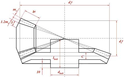
Fig. 9.12. Sketch layout of bevel gears