2015-08-21
 362
362Single-row tapered-roller bearings (GOST 333-79). Lightweight series, a=12¸18°
dc = 0.5∙(D+d)
dp = 0.25∙(D-d)
lp = 0.68∙ B 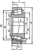
| Type designation | d | D | T | B | C | d 1 | d 2 | D 1 | Load rating, kN | e |
| Cr | C 0 | ||||||||||
| 11.75 | 6.1 | 0.45 | |||||||||
| 13.25 | 14.0 | 9.0 | 0.31 | ||||||||
| 15.25 | 21.0 | 13.0 | 0.36 | ||||||||
| 16.25 | 24.0 | 17.5 | 0.36 | ||||||||
| 17.25 | 31.5 | 22.0 | 0.36 | ||||||||
| 18.25 | 38.5 | 26.0 | 0.37 | ||||||||
| 19.25 | 46.5 | 32.5 | 0.38 | ||||||||
| 20.75 | 50.0 | 33.0 | 0.41 | ||||||||
| 21.75 | 56.0 | 40.0 | 0.37 | ||||||||
| 22.75 | 65.0 | 46.0 | 0.41 | ||||||||
| 23.75 | 78.0 | 58.0 | 0.35 | ||||||||
| 25.25 | 96.0 | 82.0 | 0.37 | ||||||||
| 27.25 | 107.0 | 84.0 | 0.39 | ||||||||
| 28.25 | 112.0 | 95.2 | 0.42 | ||||||||
| 30.50 | 130.0 | 109.0 | 0.43 | ||||||||
| 32.50 | 158.0 | 125.0 | 0.38 | ||||||||
| 34.50 | 168.0 | 131.0 | 0.41 | ||||||||
| 37.00 | 185.0 | 146.0 | 0.41 |
9.3.5. Lip seal.
Dimensions of lip seals are given in table 9.6.
Table 9.6
Standard lip seals (GOST 8752-79)
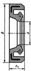
| d | D | h 1 | d | D | h 1 |
| 20;21;22 | 55;56;58 | |||||
| 63;65 | ||||||
| 70;71 | ||||||
| 30;32 | ||||||
| 35;36;38 | ||||||
| 90;95 | ||||||
| 48;50 | ||||||

9.3.6. Sprocket (Fig 9.6)
- diameter of the hub d hub = (1.5…1.7)· d shaft;
- length of the hub l hub=(1.2…1.5)· d shaft;
- thickness of the web C = 0.93· B bush,
where Bbush is the bush width (table 8.2).
9.3.7. Pulley (Fig. 9.7)
- diameter of the hub d hub=(1.8…2.2)· d shaft;
- length of the hub l hub=(1.5…2.2)· d shaft ≤ B, where B is the pulley width;
 - thickness of the rim δ=0.005· d +3 mm;
- thickness of the web C =(1.0…1.2) ·δ (for pulleys of d ≤ 300 mm);
- number of arms z (for pulleys of d ≥ 300 mm)
if 300 < d ≤ 500 mm than z =4
if d > 500 mm than z =6
- design thickness of the arm
 ,
,
where Ft is turning force obtained in p.7.8; d is diameter of the pulley; z is number of arms; [ σb ] is allowable bending stress (for cast irons [ σb ]=30 MPa)
9.3.8. Coupling.
In mechanical drives with single stage speed reducers we use a coupling with rubber-bushed studs. Dimensions of this coupling are given in table 9.7.
Table 9.7