2015-08-21
 399
399The current oscillator has high input resistance, it means that a diode is connected to a high resistance circuit and this factor defines its condition of operation. Let’s consider the diode operation at forward current pulse of a rectangular waveform, flowing through it. (Fig. 3.12a)
At the first moment of the forward current pulse passing, there is a high voltage drop across a diode, which comes down afterwards because of decreasing the base region resistance of a diode. That is defined by accumulation of unbalanced carriers in the base region. When the accumulation of minority carriers in the base is over, the diode voltage Vd, the diode base voltage Vb, and the p-n junction voltage Vjun will reach the constant values Vd_const, Vb_const (Fig. 3.12b, c, d). The voltage drop across the bulk resistance of a base disappears abruptly when the current pulse ends (Fig. 3.12b). Holes concentration in a base near a p-n junction can’t change immediately. Thus, the p-n junction voltage and the diode voltage respectively come down slowly after the current switching off. It happens as a result of minority carriers recombination. After the recombination process ending, the diode voltage comes down to zero (Fig. 3.12d). The diode operates as a gate in this condition, and its fast-response is defined as the time of reaching the steady state for a forward voltage  . In this case Vd = (1.1 - 1.2) Vconst (Fig. 3.12d).
Let’s consider the diode operation with a current oscillator under the high amplitude condition.
When the forward voltage is applied to a diode, the diode current doesn’t reach the steady state at once, because the base resistance still remains high enough.
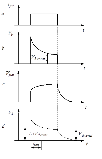
Fig. 3.12. Current and voltage oscillograms of a diode operating with a current oscillator under the high-amplitudes condition: a – input current pulse, b –diode base voltage, c- voltage at the p-n junction, d –diode voltage
After information signal coming, injection of minority carriers through the p-n junction appears and they will be accumulated in a base. As a result, the base resistance comes down, and the diode current increases, though the diode forward voltage remains constant (Fig. 3.13b). The process of base resistance modulation does not occur instantaneously, because the diffusion process of minority carriers into a base comes about rather slowly. All voltage is redistributed between the base resistance and the p-n junction as the carriers are accumulated and the base resistance comes down. The voltage drop across the base of a diode comes down and the p-n junction voltage grows. It leads to an increase in the injection process. Carriers injection is placed in equilibrium with their recombination during the action of a forward voltage pulse.
When the forward diode voltage is changed to the reverse one, the high reverse current begins to flow (Fig. 3.13b). This current is limited by a base series resistance. The minority charge carriers start to clean out in the base. The concentration of carriers in a base near a p-n junction can’t come down to balance at once because of the reverse current limitation. The reverse current begins to come down when the concentration of these carriers decrease to zero during the clean-out time tcl.out. All accumulated carriers leave the base across the p-n junction or recombine in a while trest. As a result, the reverse current comes down and reaches the level of saturation current  (Fig. 3.13b). At the same time the diode restores its reverse resistance.
After voltage switching from the forward to reverse one, the reverse resistance of a diode restores its constant value. This transient process is called restoration of a reverse diode resistance. So, the time of reverse resistance restoration  is one of the main parameters of pulsed diodes. It is equal to the time within a moment when current runs through zero, after the diode switching from the forward to reverse voltage and a moment when the reverse current will reach the given low value
  (Fig. 3.13b).
All pulsed diodes, with reference to restoration time, are divided into six groups. There are diodes with restoration time more than 500 nsec, 150-500 nsec, 30-150 nsec, 5-30 nsec, 1-5 nsec, 1 nsec and less than 1 nsec.
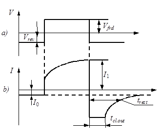
Fig. 3.13. Voltage and current oscillograms of a diode operating with a voltage oscillator under the high-amplitudes condition: a – input voltage pulse, b – current pulse of a diode