2018-02-14
 297
29719 The Department of Energy's Fusion Policy Advisory Committee judged heavy-ion accelerators the leading candidate for a reactor driver because of their durability, reliability, high-pulse-rate capability and potential for high efficiency. Heavy ions such as xenon, cesium or bismuth with kinetic energies of 2-10 GeV have the correct stopping range to drive targets. To obtain the 4 x 10¹⁴ W, which is the power needed to drive the target, requires a current on the order of 100 kA, assuming singly charged ions are used. This current is large compared with the currents that are common in conventional high-energy accelerators. Beams with these characteristics have not yet demonstrated the required brightness.
20 There are two main approaches to heavy-ion drivers: radiofrequency accelerators and induction accelerators. Physicists in Europe and Japan are studying the rf accelerator because of their large body of experience with the many existing high-energy physics accelerators. Physicists in the US are examining the induction accelerator because of its simplicity and ability to handle high-current beams. In such accelerators space-charge-dominated beams are periodically accelerated by induction cells and transported by a sequence of alternating-gradient quadru-poles. At any beam velocity there is a maximum current that can be successfully transported in an alternating-gradient lattice. The current limit is reached when space-charge forces of the beam become equal to the applied focusing forces For a properly designed system this current, in mks units, is given by
I max ≈4 x 10-12 aB v 2
where a is the beam aperture radius, В is the pole-tip magnetic field of the quadrupoles, and v is the ion velocity. For electrostatic quadrupoles, В is replaced with E/ v. The current limit is often referred to as the Maschke limit after Alfred W. Maschke, who proposed heavy-ion accelerators as inertial fusion drivers.
21 For a specific example of the current limit, consider the case of 10-GeV ions, a beam aperture of 5 cm and a magnetic field of 2 T. At 10 GeV the velocity of a heavy ion is about 108 m/sec, so that Imax ≈ 4 kA. To achieve 4 x 10¹⁴ W per pulse requires a total current of 40 kA, so multiple beams—more than ten—are necessary. To focus each beam also requires multiple beams because of the space-charge limits. Fortunately multiple beams can be accelerated simultaneously through the same induction cells, which are very efficient at high beam current. This technique, combined with the use of superconducting quadrupoles for transport, can produce overall accelerator efficiencies of 20-30%.
22 Several linear and recirculating architectures that are being considered try to minimize cost. In the linear versions the beams are accelerated in a single pass. In the recirculating versions the beams pass through the same induction cells many times.
| The Sombrero reactorprotects the graphite first wall from target xrays with xenon gas that allows the laser beams to reach the target. Li2O granules fall through channels in the carbon-carbon-composite wall. The small circles are openings for 60 uniformly spaced laser beams that illuminate the direct-drive target. |
| Figure 4 |
Reactors
23 A fusion target burns to completion in a few tens of picoseconds to 100 psec. Interaction with material surrounding the fuel capsule can lengthen the duration of the pulse of x rays and target debris to about a nanosecond. Typical target yields in a reactor will be a few hundred megajoules. The reactor must contain the effects of this microexplosion, capture the thermonuclear energy and breed tritium. A variety of structural walls and a breeding and thermal transport "blanket" thick enough to stop 14-MeV neutrons perform these functions. Neutrons carry away about two-thirds of the thermonuclear energy. The rest is in the form of x rays and target debris. One can vary the x-ray and debris spectra and pulse lengths considerably, depending on how much material one places around and near the target. Nevertheless the deposition range of this nanosecond-long pulse of energy is small. Therefore the first wall will be subjected to very high instantaneous power loads. Over 50 imaginative designs can plausibly handle this problem. We will describe three recent representative examples: Sombrero, Osiris and Cascade.
24 Sombrero. The simplest way to handle the high peak power load is to protect the wall with a buffer gas so that no material is vaporized—a dry-wall reactor. In the Sombrero design (shown in figure 4), a wall made of carbon composite at a radius of 6.5 m is protected from the effects of the 400-MJ targets by 0.5 torr of xenon gas. The laser beams penetrate the gas, but the xenon absorbs the x rays from the target and reradiates their energy to the wall on a longer time scale, thereby reducing the wall loading. Without the gas, the wall would have to be over 12 m away. Within the 1-m-thick first-wall structure are channels through which flow gravity-fed solid Li2O ceramic granules. The neutrons deposit their energy in the granule bed and create tritium through exothermic (n,Li) reactions. Most of the x-ray and debris energy is conducted through the first wall to the flowing bed. After exiting the reactor, the granule bed is fluidized with helium and transported around a loop, where heat and tritium are extracted. In this direct-drive design, 60 uniformly spaced laser beam lines penetrate the reactor wall and blanket.
25 The final optical element in each beam line is a grazing-incidence metal mirror that reduces neutron effects by presenting a large surface area to the incident beam. It is about 25 m from the center. The next-to-last optical element must be a sizable distance from the grazing-incidence mirror to be out of the target's line of sight. As a result, the building housing the reactor must be very large—about 100 m in diameter and 100 m tall. With a rearrangement of the laser illumination angles, the Sombrero design could also be used with indirect-drive laser targets. The table on page 48 shows typical operating parameters for a Sombrero direct-drive power plant with a KrF laser driver.
The first structural wall in this type of reactor will be exposed to direct neutron bombardment by 14-MeV neutrons and, as a result, will in time lose its structural properties. It is estimated that the inner wall of such reactors will have to be replaced every few years.
26 Osiris. Figure 5 shows the Osiris reactor, in which hohlraum targets are indirectly driven by six heavy-ion beams entering from each of two principal directions. The reactor is small to reduce capital costs. To handle the large power density, a self-renewing liquid first wall flows at a radius of about 4 m. The working fluid is a eutectic mixture called "flibe," which is two- thirds LiF and one-third BeF2. It enters the reactor at 500 °C and flows through a woven carbon fabric tent-like structure. The porous material allows flibe to weep through, wetting the entire inside surface with a film about 2 mm thick. When the target explodes, the x rays vaporize a layer of flibe a few micrometers thick—a few kilograms' worth—within about 10 nsec. The vapor fills the chamber and reaches a steady pressure in a time on the order of tens of microseconds. The neutrons deposit their energy in the 0.5-m-thick flibe layer, causing it to expand and force more flibe through the pores of the carbon cloth to replace the fluid that vaporized. The flibe vapor is directed toward cold flibe sprays near the bottom in a few milliseconds, and the cold flibe droplets condense the vapor. Calculations predict that the low pressure—less than 10 -3 torr— required for propagation of the heavy-ion beams is restored within 100 msec. A low-activation carbon-carbon-composite vacuum vessel contains the entire blanket.
27 Heavy-ion-driven reactors have the advantage that no material object important to beam propagation or focusing need be in a direct line of sight with the target. The beams can be bent out of the direct path with magnets that are themselves out of the line of sight. Line-of-sight "get lost" (non-reflective and non-scattering) dumps handle the x rays, neutrons and debris, while fast-closing valves and differential pumps isolate the accelerator vacuum from the vapors in the reactor. The table on page 48 contains typical operating parameters of a heavy-ion-driven Osiris power plant.
28 In Osiris the structural wall is protected from neutron damage by the thick blanket of flibe, so the wall should last the 30-year lifetime of the plant without replacement. The reactor's top can be removed, and the entire carbon cloth structure, which is exposed to higher fluences, can be lifted out for replacement every few years.

Figure 5
The Osiris reactor. The carbon-composite structure is protected by a thick blanket of molten flibe—a mixture of LiF and BeF2—guided by a carbon fabric "tent."
Cascade.
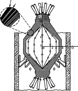
29 Cascade uses a flowing blanket of ceramic granules, as does Sombrero, but in this design they are inside the structural wall, as seen in figure 1. The granules flow by force of gravity into the ends of a rotating, cement-mixer-like structure about 5 m in radius. The chamber's rotation keeps the 1-m-thick granule bed against the wall, flowing toward the largest radius. The reactor cone angle is set at the angle of repose (the angle of a freely formed sand cone) to maintain a uniform blanket thickness. At the waist the granules fall out of slots and are thrown through tubes (not shown) into a heat exchanger, where they transfer their heat to helium gas, which in turn generates electricity through a closed Brayton cycle. The granules can operate at very high temperatures—1715 К maximum for the carbon first layer—a gross thermal-to-electric efficiency of 54%. The entire reactor vessel and the heat exchangers are contained inside the vacuum vessel to avoid the problem of transporting granules through interlocks. The rotating reactor wall is made of low-activation silicon carbide tiles that are held in compression by an external network of composite tendons. Seven heavy-ion beams enter the reactor from each end.
30 In Cascade the first few micrometers of the granule surface are vaporized within about 10 nsec. The vapor fills the chamber in tens of microseconds. During this time the shock in the first layer is mitigated by compaction of the granule bed. Neutrons deposit their energy in the granule bed during the same interval. When the rebounding vapor reaches the bed again, it flows in hundreds of microseconds into the porous bed of relatively cool granules. The enormous surface area recondenses the vaporized material to restore pressures of 1-10 pascals in less than 100 msec. The granule bed then relaxes to its original density.
31 Some granules may break apart due to the shock. Outside the reactor fine particles are removed and recompacted into granules of the proper size. Target debris and tritium bred in the granules are removed through the vacuum system. All structural parts in Cascade are protected by a blanket that is thick to neutrons and should not fail from neutron damage during the lifetime of the plant. The table shows characteristic operating parameters of a heavy-ion-driven Cascade power plant. The main issues to study in the development of Cascade are the integrity and lifetime of the granules and the effects of abrasion on the reactor structure