2020-07-12
 317
317Virtual reality (VR) was once called the big idea in ICT, but no commercial applications were discovered during the years of research. VR now has been replaced by a new concept: augmented reality (AR). AR stands in the real (not virtual) world, adding digital value to what people see around them.
AR software has been created which can locate and recognise objects, instantly labelling them with relevant information obtained from the web.
Combining data from a camera, GPS, tilt sensors, digital compass and wireless broadband, it can determine exactly what is being looked at. Once the object has been identified, the internet is searched for relevant information. Once retrieved, the information is displayed as a label superimposed on the image.
When pointed at a mountain, for example, the device adds its name, height and other information to its image. The equipment can also find a nearby friend in the street, or guide you to a destination like a SatNav.
In the past, only static data (e.g. from Wikipedia) was used for the labels. More recently, ways of retrieving live data (such as aircraft departure times) have been developed.
Current research is being carried out into methods of building social networks into the system, so that you can see live information about the people when the camera is pointed at them (if their smartphone is also switched on).
The small size of the smartphone screen, however, is still a problem, and more work needs to be done to solve it.
In the future, the main areas of research are likely to give smartphones the ability to find people’s locations anywhere in the world and to provide relevant information about everyone you point your camera at.
Task 6. a) Read the article. What words or ideas do the reference pronouns 1-6 refer to? b) Prepare a bilingual glossary based on the terms and special words in the article. Translate the text into Russian. Comment on the translation techniques and transformations you applied.
New Developments in Oil Mining Technology
Smart Oil Fields
If an oil company discovers a large single reservoir of oil and gas, the solution is simple: drill a vertical well down to the reservoir and bring up the oil. But what can be done when an oilfield consists of hundreds or even thousands of small, isolated pockets of oil? It would be too expensive to drill hundreds of vertical wells to reach all the small pockets.
The innovative solution to this problem is the ‘snake well’. Unlike the conventional vertical well, this (1) is a horizontal well that weaves laterally back and forth across a number of oil-containing zones. Guided by smart technology, a single snake well can access multiple pockets of oil and achieve output equivalent to several individual wells, which (2) has the dual advantage of reducing cost and ensuring that no oil is overlooked.
A snake well uses steerable drills that (3) can be positioned with great accuracy. Special imaging software generates detailed computer models of underground geology and reservoirs. This (4) enables drills to hit a target far underground that is less than two metres across.
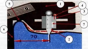
Located 90 km off the coast of Brunei, the Champion West oilfield is Shell’s flagship project using Smart Fields technology. For 30 years, Champion West lay dormant, its rich oil reserves locked 2,000 to 4,000 m beneath the seabed in a complex web of small reservoirs (see illustration above).
In the past, these small pockets of oil were too expensive to develop. But now Champion West has been changed into one of the world’s most advanced oil and gas fields by means of Smart Fields technology and new drilling techniques.
Buried deep beneath Champion West’s seabed, sensors relay digital information about temperature, pressure and other factors to control centres on land by means of a network of fibre-optic cables.
This (5) enables continuous monitoring of production, and engineers can make speedy decisions on how best to extract the maximum amount of oil, monitor its movement within the reservoir and instantly notice production problems, such as blockages.
They (6) can take action to solve problems, for example by the remote electronic activation of hydraulic well valves. If gas or water threatens to break into the well, for example, the valve for that section can be closed down using a remote control. Swellable seals are used to isolate the zones from one another, and prevent fluid from one zone from flowing into another adjacent zone.
SECTION II. USER MANUALS.
Task 1. Prepare a bilingual glossary based on the terms and special. Translate the following text into Russian. Comment on the translation techniques you applied.
BUNKER HILL SAFES
Electronic Digital Safe
Installation and Operation Instructions
| TO PREVENT SERIOUS INJURY, READ AND UNDERSTAND ALL WARNINGS AND INSTRUCTIONS BEFORE USE |
Operation
To Open the S afe: Input the numbers “159” on the Electronic Key Pad, then press either the “A” or “B” Key. Once the Green light is on, turn the Knob and pull the Door open. Note: The knob must be turned within 5 seconds of the Green light coming on. If the knob is not turned, the entry code will need to be re-entered.
To Close: Close the Door and turn the Knob in the opposite direction. The Safe is now locked.
To C hange the C ode: The Safe comes preset with a default code of “159”. To change the Code, first follow the instructions for opening the Safe. On the inside of the Door toward the hinge, you will see a small Red Button. Press this Button until the Yellow Light on the Front Control Panel lights up. Now you can input the new Code (1 to 8 characters) into the Front Control Panel, followed by either the “A” or “B” Key. The Safe will beep twice to confirm that the Code has been changed.
Important: If the Safe beeps three times, then the Code has not been accepted, and you must repeat the steps above.
To Change the Batteries: If the Red Light and the Green Light are both lit at the same time, it is time to change the Batteries. Follow the instructions for opening the Safe. The Battery Compartment is located on the inside of the Door. Slide the Battery Cover off of the Battery Compartment, remove used Batteries, and insert four new “4, AA” Batteries. Once you have changed the Batteries, be sure to test the Code before you close the Door again.
U sing the E mergency Key:
a) The Safe comes with two Emergency Keys in case the code is forgotten or the batteries are dead. To override the electronic locking device, detach the Front Panel from the Safe. There is a sticker to the left of the keypad, with SKU # 45891 printed on it. Gently peel off that sticker. See Figure 1.
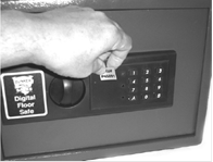
Figure 1.
b) Remove the screw under the sticker, as shown in Figure 2.
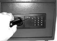
Figure 2.
c) Gently remove the Panel to reveal the Secret Key-Operated Lock. Insert Emergency Key into the Secret Key-Operated Lock and turn. Turn Knob and pull Door open. Replace the keypad and the sticker when finished. See Figure 3.

Figure 3.
IMPORTANT: NEVER LOCK THE EMERGENCY KEYS IN THE SAFE!
Installat i on
The safe has four concrete fasteners that are inside of the safe when you open it. There is also a mounting template included with the safe. Place the mounting template against the area you will be mounting the safe and tape it into place.
WARNING! Before drilling or driving nails, make sure there are no wires, cables or pipes in the path.
To attach the safe to a wood surface, hammer a nail (not included) to mark the hole placement. Drill an 1/8” diameter pilot hole into each mounting hole location. Place the safe over the mounting holes and secure the safe using four 1/4” diameter self-tapping screws (not included).
To use the concrete fasteners, drill a small pilot hole through the template to mark the hole placement. Next drill four holes in the correct location, using a concrete drill bit. Drill the holes the same diameter as the fasteners and 2” deep. Hammer the fastener in the hole with the flat side going into the hole first. Use a wood block between the bolt and the hammer to protect the threads.
Place the safe over the bolts (with the nut removed from the bolts) and tighten a nut onto each bolt. As you tighten the nuts onto the bolts, the fasteners will expand inside the cement, securing the safe into place.
Note: There are no replacement parts available for this product.
Task 2. Prepare a bilingual glossary based on the terms and special words. Translate the following text into Russian. Comment on the translation techniques you applied.
| PELTIER COOLER/HEATER PCH-1/PCH-2 Operating instructions | 
|
Сontents
1 Safety......................................................................................................................3
2 General Information...............................................................................................4
3 Getting started........................................................................................................5
4 Operation of PCH-1/2............................................................................................6
5 Maintenance...........................................................................................................8
6 Specifications.........................................................................................................9
7 Guarantee and service..........................................................................................10
Safety
The following symbols mean:
 Caution: Read these operating instructions fully before use and pay particular attention to sections containing this symbol.
 Caution: Surfaces can become hot during use.
 Use only as specified by the operating instructions, or the intrinsic protection may be impaired.
 After transport or storage in humid conditions, dry out the unit before connecting it to the supply voltage.
 During drying out the intrinsic protection may be impaired.
Connect only to a power supply with a voltage corresponding to that on the serial number label.
Ensure that the mains switch and isolating device (power supply connector) are easily accessible during use.
Connect only to a power supply which provides a safety earth (ground) terminal.
Use only with the power supply provided or a replacement supplied by Grant.
Before moving, disconnect at the power supply socket.
If liquid is spilt inside the unit, disconnect it from the power supply and have it checked by a competent person.
It is the user's responsibility to carry out appropriate decontamination if hazardous material is spilt on or inside the equipment.
Use only standard and good quality tubes. Remember that thin-walls tubes have a higher thermoconducting factor;
Don't heat the tubes over the melting point of the material they are made of. Use thermoresisting polypropylene tubes.
Don't fill tubes more than 3-5 mm over the level they are immersed in the thermoblock;
Before using any cleaning or decontamination method except those recommended by the manufacturer, user should check with the manufacturer that the proposed method will not damage the equipment.
The unit has an air intake for cooling and ventilation. Do not block or impede the ventilation grille.
Clean the unit only with a damp cloth, do not use chemical cleaning agents.
2. General Information
Introduction
Peltier cooler/heater PCH-1/2 is designed for maintaining the set temperature, in the temperature range from -10°C to +100°C on the aluminum block with special sockets for tubes. The device can also be used for maintaining stable temperature in the room where the temperature is fluctuating, e.g. +20 ±0.1°C at room temperature (RT) changing from +18°C to +22°C.
PCH-1/2 has obvious advantages when, for example working with micro quantities of reagents used in the Eppendorf tubes.
The device can be used in:
• molecular and cell biology for sample cooling,
• biochemistry for enzyme processes analysis.