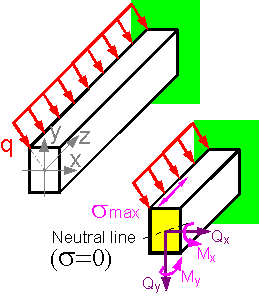
 If an external force passes through the center of the cross-section for the shown scheme there is no torque Mz=0 and no projection of inner forces at axis z: Pz=0.
Upper layers of the cantilever beam are under tension and lower layers are under compression. If forces don't lie in a plane with a principle axis, the neutral axis swings through some angle. The stress is highest in points that are furthest from the shown neutral axis. The top left point of the section has the maximum tensile stress.
 The summed stress pattern can be obtained by considering the tension and bending of the beam. For long cantilever beams bending stress is usually higher than tensile stress if both forces are equal.
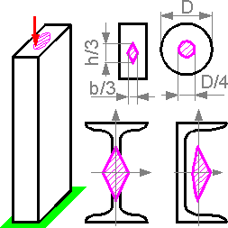 If a compressive force was applied outside the center of the cross-section, a tensile bending stress may occur. There is an area in which the addition of a compressive force does not cause tensile stress in the column. The shape of the zone for cylindrical sections is a circle.
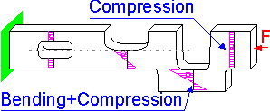 If the line of force application and the center of the cross section do not coincide by a distance h, there is bending moment F*h that causes compressive and tensile stresses.
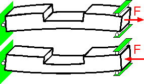 Additional bending moments cause a change in the shape. The shape depends on the sign of the bending moment, positive or negative.
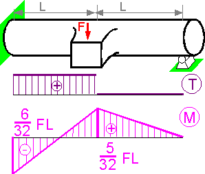 The principle stress is at a maximum in the embedded end of the structure, where torque T and bending moment M are highest.
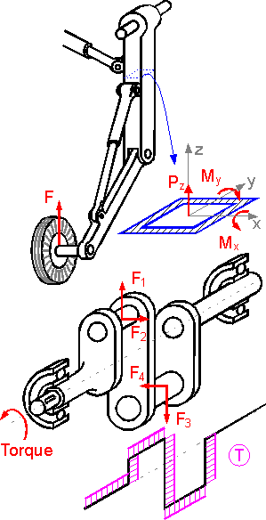 Force and moment diagrams for a complex structure can be obtained by the static equilibrium conditions. Maximum number of inner forces and moments is 6. There are geometries where less than 6 components of inner forces and moments act.
 2015-08-13
 396
396


