2015-08-13
 518
518At the calculation of magnetic circuit a magnetizing current is determined, stipulating MMF of asynchronous motor. For this purpose it is necessary to calculate MMF of magnetic circuit as a sum of magnetic voltage drops across separate areas of magnetic circuit of asynchronous machine: air-gaps, tooth areas, backs of armature and rotor:
F∑ = Fδ + Fz 1 + Fj 1 + Fz 2 + Fj 2
where Fz 1 and Fz 2 − magnetic voltage drops respectively in the toothes of stator and rotor; Fj 1 and Fj 2 − magnetic voltage drops respectively in the back of stator and rotor.
The value of magnetic flux is determined also in an air-gap:
Фδ0 = kЕ 0 ∙Uph 1/(4 ksh∙kw 1∙ wph 1 ∙f), (52) where kЕ 0 = 1/(1 + k σ0), k σ0 = Хs 1/ Хm = I 0 m Хs 1/(Uph 1 – I 0 m Хs 1) – a dispersion factor of flux linkage of primary circuit, approximately accepted equal to kЕ 0 = 0,95÷0,97; I 0 m – magnetizing current in the o.c. mode.
Magnetic induction in the air-gap of motor in the o.c. mode is
В δ0 = [Фδ0/(α i∙li ∙τ]∙104 = [1,57∙Фδ0/(li ∙τ)]∙104. (53)
Calculation of magnetic voltage drops in stator and air-gap is made in accordance with methodology, expounded in § 2.6 [1]. Magnetic voltage drops in the toothes of rotor at straiht and trapezoid toothes is calculated also in accordance with § 2.6 [1].
In case of application of "squirrel-cage" round slots are used on a rotor (fig. 9, а). At the calculation of MMF of toothes the following values are determined:
rating width of tooth
bz 2= π[ Dr − 2(hlm 2 + d /3)]/ z 2 − 0,94 d;
tooth step of rotor
tz 2 = π∙Dr / z 2
coefficient, taking into account the increase of induction in rotor toothes relativly to induction in an air-gap
kz 2 = tz 2∙ l 1 / (ksf ∙ bz 2∙ l 2)
where l 1 and l 2 − active length of stator and rotor; at l 1 = l 2
kz 2 = tz 2 / (ksf ∙ bz 2)
magnetic induction in rotor toothes is
Bz 2 = kz 2∙ В δ;
length of magnetic line of force in rotor toothes is
Lz 2 = 2 d
MMF of rotor toothes (on the poles pair)
Fz 2 = H z2 ∙Lz 2,
where Hz 2 is determined by the curve of magnetizing.
MMF of rotor back is determined:
Fj 2 =Hj 2 ∙Lj 2,
where Lj 2 = π∙ Dr,av / 2 p; Dr,av = Dr – 2 hz 2 – hj 2; hj 2 − height of rotor back; Hj 2 − field intensity in the rotor back.
The value of hj 2 is determined by a formula
hj 2 = [(Dr – 2 hz 1 – Di 2) / 2] − 2∙ nax,v∙dax,v / 3,
where Di 2 − internal diameter of rotor (bore for a shaft); nax, v − number of rows of axial vent channels; dax, v − diameter of axial of a vent channel; in the absence thereof of vent a member 2∙ nax,v∙dax,v / 3 equals to the zero.
The value of the field intensity is determined by induction in the armature back
Bj 2 = Фδ0∙104/(2 Sj 2),
where Sj 2 = hj 2∙ ksf ∙ l 2 − area of cross-section of rotor back.
At the calculation of MMF of rotor back of bipolar machines it is accepted, that a magnetic flux passes also through the shaft of motor, but induction in a yoke remains unchanging along a pole pitch. Intensity Нj 2 is determined by the basic magnetizing curve. In this connection for the rotor back of bipolar motor it is accepted
hj 2 = (Dr – 2 hz 2)/2, Lj 2 = 2 hj 2
At the calculation of asynchronous machine one has to set oneself the value of α i. After implementation of calculation it is necessary to specify the value of α i. As researches show, the value of α i substantially depends on the saturation of tooth areas and backs of stator and rotor. If designate ratio of MMF of toothes, backs and MMF of air-gap by coefficients
k μ z = (Fz 1 + Fz 2) / F δ; k μ b = (Fj 1 + Fj 2) / F δ,
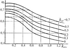 that for determination of α i it is possible to take advantage Fig. 12 of curves, shown on a fig. 12.
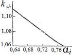
A value of curve shape coefficient of the field ksh depends on a value α i (fig. 13).
 Total MMF of magnetic circuit F ∑ allows to define the magnetizing current value (reactive constituent of o.c. current)
I 0 m = 1,11∙ p ∙ F∑ / m 1∙ wph 1∙ kw 1), (54)
Fig. 13 where m 1 − number of stator winding phases.
At m 1 = 3
I 0 m = 0,37∙ p∙F∑/ (wph 1∙ kw 1) (55)
After determination of magnetizing current a checking of
dispersion coefficient of flux k σ0 is made:
k σ0 = I 0 m ∙ Хs 1 / (Uph 1 – I 0 m ∙ Хs 1).
If values of coefficients α i, ksh, k σ go away with accepted at the beginning of calculation, then it is necessary again to make the calculation of magnetic circuit and magnetizing constituent of primary current.
Current of idling
I 0 = √ (I 20 m + I 20 a ), (56)
where I 0 a = Р 0/(m 1∙ Uph 1) − active constituent of o.c. current, Р 0 − losses of the synchronous idling, Р 0 = Pst + m 1∙ I 20∙ r 1; Рst − losses in steel.
Power-factor of the synchronous idling
cos φ0 = I 02 / I 0.
Coefficient of saturation
k μ = F ∑0 / F δ.
Constituent of magnetizing current on air-gap (А)
I δ = I 0 m / k μ
Constituent of magnetizing current on steel
Ist = I 0 m (F ∑0 − F δ) / F ∑ = I 0 m (1 – 1/ k μ).
7. CALCULATION AND PLOTTING OF MAGNETIC CHARACTERISTIC (B-H curve) OF ASYNCHRONOUS MACHINE
For the further calculations of asynchronous machine it is necessary to calculate and plot B-H curve which represents dependence of magnetic induction of air-gap or E.M.F. of machine on a magnetizing current
B δ = f (Im) or Eph 1 = φ(Im)
For the plotting of B-H curve it is necessary to calculate magnetic circuit also for a few values of induction B δ or magnetic flux Фδ besides their values for the mode of o.c. of motor.
Foremost expediently to calculate magnetic circuit for nominal generator mode. In this case it is possible to choose kE = 1 and so:
Фδ nom = kЕ ∙ Uph 1/4∙ ksh∙kw 1∙ wph 1∙ f) = Uph 1/4∙ ksh∙kw 1∙ wph 1∙ f) (57) В δ nom = [Фδ nom / (α i∙li ∙τ)]∙104 (58)
MMF of air-gap, magnetic inductions in the toothes of stator and rotor are changed in direct dependence on magnetic induction of air-gap. Magnetic inductions in the backs of stator and rotor depend on the design value of pole overlap coefficient:
Вj 1 = Вj 10(α i /α i 0)(В δ/ В δ0); Вj 2 = Вj 20(α i /α i 0)(В δ/ В δ0),
where Вj 10, Вj 20, α i 0 − values for the o.c. mode.
Calculationof MMF of separate areas of magnetic circuit and total MMF on the poles pair is made the same as for the o.c. mode.
Magnetizing current
Im = Im 0 F ∑ / F ∑0.
Value of E.M.F. Еph 1 for every value of B δ(Фδ) is determined by the known expression
Eph 1 = 4∙ ksh∙kw 1∙ wph 1∙ f ∙Фδ. (59)
It is possible to count up inductive resistance of magnetizing circuit for every value of Im
Xm = Eph 1 / Im.
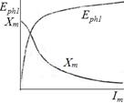 The curves of Eph 1 and Хm depending on the current of Im are presented on a fig. 14. These curves characterize the degree of saturation of magnetic circuit of machine. The value of magnetizing current Im = Im 0 and value of inductive resistance of magnetizing circuit Хm = Хm 0 correspond to the point of idling (fig. 1, b) of the generator mode at Eph 1 = Eph 0. Curves of Ep h1, Хm = f (Im) are used for the calculation of machine characteristics in traction and Fig. 14 generator modes