2015-08-13
 409
409The necessary number of coils in a phase is determined by E.M.F. of the generator mode
wph 1 = Eph 1 / (4∙ ksh∙kw 1 ∙f∙B δ) = kEUph 1 / (4∙ ksh∙kw 1 ∙f∙ Фδ) (22)
where Фδ = α i ∙τ∙ li∙B δ∙10-4.
In asynchronous machines coefficients α i and ksh depending on a saturation usually are within the limits of α i = 2/π ÷ 0,76 and ksh = 1,11 ÷ 1,065. In most cases coefficient of saturation k μ = Fz / F δ ≤ 1,5. Then α i and ksh it is possible to define depending on k μ under equations
α i = 0,443 + 0,194 k μ, ksh = 1,18 − 0,07 k μ. (23)
It is preliminary possible to take: α i ≈ 0,715 and ksh ≈ 1,09. The choice of number of stator slots z 1 for asynchronous machines is closely related with choice of number of rotor slots z 2. Ratio between z 1 and z 2 it must be chosen for motors, coming from the following considering:
1. Absence of failures in the curve М = f (n), conditioned by parasite asynchronous and synchronous moments of tangential forces.
2. Minimum noisiness during a running, arising up under the action of radial forces.
3. Minimum additional losses are in steel of toothes.
For the decline of asynchronous parasite moments at starting and rotation of motor next inequalities are kept:
а) at starting
z 2 ≠ z 1; z 2 ≠ 0,5∙ z 1; z 2 ≠ 2 z 1; z 2 ≠ 2 m 1 p∙q,
where q − any positive number;
b) at the rotation of motor
z 2 ≠ 2 m 1 p∙q + 2р; z 2 ≠ z 1 + 2р; z 2 ≠ 2 z 1 + 2р; z 2 ≠ 0,5∙ z 1 + p; z 2 ≠ z 1 + p.
In order to avoid appearance of radial forces, it is needed to keep inequalities
z 2 ≠ 2 m 1 p∙q + 1; z 2 ≠ 2 m 1 p∙q + p + 1; z 2 ≠ 2 m 1 p∙q + 2 p + 1.
For the asynchronous machines with squirrel-cage rotor a ratio of stator and rotor numbers of slots are used in accordance with these tables 4.
Tabl. 4
| 2 p | z 1 | z 2 |
| 21 (15, 22, 23, 30) 18 (17, 19, 22, 30, 36) (36) | ||
| 16, 22, 30 (17, 36) 26, 42 (44) | ||
Note. The numbers of slots, which dissatisfy to all requirements simultaneously, are indicated in brackets.
By the most widely-used numbers of stator slots are z1 = 18, 24 and 36.
Thus, for widespread three-phase machines of two- and four-polar executions the number of slots on a pole and phase q 1 = z 1/(2 p∙m 1) is equal to:
for 2 p = 2: q 1 = 3, 4, 6; for 2 р = 4: q 1 = 1,5, 2, 3.
It is necessary to avoid application of broken number of slots on a pole and phase because of winding making complication, increase of differential scattering.
|
Number of wires in a slot must be an integer, and at the two-layer winding − by an even number
us l =[ wph 1 / (p∙q 1)]∙ a 1 (24)
Number of coils wph 1 derived from the condition of wires placing in slots, must be equal to the loops number wph 1, got from the condition of E.M.F. Еph 1.
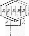
Stator windings of asynchronous generators, are desighned, as a rule, figure-of-two-layer lap allocated ones. On a fig. 7 one phase of the three-phase two-layer lap winding of asynchronous generator is shown at р = 3, q 1 = 2, consisting of one branch a and two parallel branches b.
For providing of sinusoidal shape of output voltage curve a shortening of its step is foreseen on 1/5τ (fifth harmonic is done away). If to express the step of winding in slots, then the shortened step is
y 1 = y τ – yτ / 5 = 0,8 z 1 / 2 p,
where y τ = z 1 / 2 p − step in slots by a pole division. A step of winding must be an integer. Therefore it is taken to nearest greater integer.
The values of stator winding steps, the coefficients values of shortening kst and distributions kds at the different values of q 1 are driven to the table 5.
Tabl. 5
| q 1 | q 1 | ||||||
| y τ y 1 y 1 / y τ | 0,833 | 0,778 | 0,833 | kst kds kst kds | 0,966 0,966 0,933 | 0,940 0,960 0,902 | 0,966 0,958 0,925 |
If phase voltage of asynchronous generator is used, in which the third harmonic most strongly shows up and hard requirements are produced to the shape of phase voltage curve, then in this case shortening of winding step is foreseen on 1/3 of pole p.
For removal of tooth harmonics in the voltage curve the bevel of stator or rotor slots is used. The bevel of slots results also in diminishing of parasite moments, operating on the shaft of asynchronous generator and drive device. A bevel of slots increases inductive resistances of leakage of windings, increases additional losses in steel and diminishes E.M.F. in windings. Therefore the value of slots bevel is not done by large. The bevel of slots is accepted usually equaled to the tooth spacing of stator at the bevelled slots of rotor or tooth spacing of rotor at the bevelled slots of stator. Diminishing of rotor E.M.F. because of slots bevel is taken into account by the coefficients of bevel: at the bevel of stator slots
kar 1 = 1 – 1,646(p∙b*ar 1 / z 2)2 ;
at the bevel of rotor slots
kar 2 = 1 – 0,0458∙(b*ar 2 / q 1)2,
where b*ar 1 = bar 1/ tz 2, b*ar 2 = bar 2 / tz 1, bar 1 and bar 2 − bevel of slots on the arc of cylindrical surface accordingly on stator and rotor. At a bevel on one tooth pitch b*ar 1 = 1 и b*ar 2 = 1.
It is possible to replace a squirrel-cage rotor winding by polyphase winding with the number of phases m 2 = z2/ р. A phase of this winding along one pair of poles consists of one bar. Therefore the number of phase loops on the pair of poles is accepted by equal to 0,5, and its coefficients of shortening and distribution are equal to unit.
The rotor winding factor equals to rotor bevel coefficient kar 2 and can be without large errors accepted by equal to unit kw 2 = kar 2 ≈ 1.
It is possible to define the number of bars of rotor winding of asynchronous generator on the basis of recommendations in regard to the choice of this value for asynchronous motors (table 6).
Tabl. 6
| Number of poles 2 p | Number of stator slots | Straight slots | Beveled slots |
| [16], 28, 32 22, 38 26, 28, 44, 46 32, 34, 50, 52 38, 40, 56, 58 | (15), 17, 19, 21, (23), 26, (30), (17), 18, (19), (22), (30), 31, 33, 34, 35,(36), (18), (20), 21, 23, (24), (36), 25, 27, 29, 43, 45, 47, 37, 39, 41, 55, 57, 59 | ||
| [32] 26, 44, 46 (34),(50),52,54 34,38,56,58,62,64 50, 52, 68, 70, 74 | 16, [20], (17), (21), 22, 30 33, 34, 35, (36) (24), 27, 28, 30, [32], 42, 45, 48 (33), 34, 38, (51), 53 (36), (39), 40, [44], 57, 59 48, 49, 51, 56, 64, 71 | ||
| 26,30,40,42,46,48 44, 64, 66, 68 56,58,62,82,84,86, | 47, 49, 50 42, 43, 65, 67 57, 59, 60, 61, 83, 85, 87 | ||
| 34, 62, 64 58, 86, 88, 90 | 35, 61, 63, 65 56, 57, 59, 85, 87, 89 |
 For exclusion of tooth harmonics in the curve of generator voltage a bevel of slots is foreseen, as a rule. At the numbers of slots, shown in parentheses, the worsened starting performances of asynchronous machine turn out, operating in the starting regime. It is not recommended to apply numbers of slots, put in square brackets, for machines which operate in the brake mode.
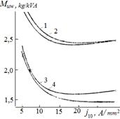
The value of current density in the Fig. 8 stator winding is got out, on the basis of requirements to mass and efficiency of generator, and also depending on the method of cooling. At powers from 1 up to 12 kVA and self-ventilations the current density in the stator winding is recommended equal to j 1 st = 7÷10 А / mm 2. In generators of power 12÷80 kVA, cooled by blow, current density is chosen within the limits of j 1 st = 12÷15 А / mm 2. The increase of current density is expedient only to the defined values (fig. 8, where Pnom =1000 VA; cos φ = 0,9; f = 400 Hz; m = 3; q = 3; р = 1; Uph = 115 V; Bz = 1,4 Т; 1: В δ = 0,6 Т; A = 100 А/сm; m = 3; q = 3; р = 1; Uph = 115 V; Bz = 1,4 Т; В δ = 0,6 Т; A = 100 А/сm; 2: В δ = 0,5 Т; A = 100 А/сm; 3: A = 300 А/сm; 4: В δ = 0,6 Т; A = 300 А/сm for an asynchronous generator with self-cooling), because the further increase of current density does not cause diminishing of specific mass and at the same time diminishes efficiency and increases overheating machines.