2015-08-13
 502
502For plotting of operating characteristics of asynchronous machine it is at one’s ease to take advantage of the circle diagram which communicates between the parameters of machine and its output characteristics.
On a fig. 15 the refined circle diagram is brought; (under Костенко [19]), worked out I. Л. Витенбергом for the practical use of asynchronous machine.
For the plotting of this circle diagram it is necessary to have next data: Uph 1, I 0 m , I 0 a , r 1, Xs 1, r’ 2, X’s 2. The values of active and inductive resistances in respect to the examined circle diagram are undertaken specified:
r 1 Х's 1 = Хs 1(1 + k σ),
r ''2 = r '2(1 + k σ)2, Х''s 2 = Х's 2(1 + k σ)2,
1 + k δ = 1 + I 0 m Xs 1 / (Uph 1 – I 0 m Xs 1), X '' k = X ' s 1 + Х''s 2.,
Here (1 + k σ) − the so-called primary dispersion Gayland’s factor.
Active resistances of stator and rotor windings r 1 and r '2 are calculated for the expected temperature of overheat.
For very little motors: (r 12/ Хm) > 0,03(Х '' k); Х '' k = Х's 1 + Х''s 2 + r 12 / X μ, where X μ = (Uph 1− I 0 m ∙ Хs 1) / I 0 m.
For this circle diagram correlations are correct:
а) diameter of circle of the circle diagram
Dc = Uph 1 / X '' k;
b) tangent of turn angle of line of center
tg 2 ψ = 2 I 0 m∙r 1/ Uph 1;
c) tangent of slope angle of useful power
tg αs= 1= r''k / X '' k;
d) tangent of slope angle of line of moments
tg αs= ∞= r 1 / X '' k;
The plotting of the circle diagram (fig. 15) is made in the next order (practical method):
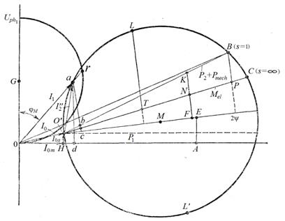
Fig. 15
- Set by the scale of current mA (1 mm − mA).
2. From the point of G, located on a y-axis in the distance 50 mm from the origin of coordinates 0, it is plotted a semi-circle by the radius of R = 50 mm, a scale of power-factors соs φ.
3. On abscise axis a segment ОН = I 0 m / ma is plotted, representing reactive component of o. c. current.
4. From the point of Н a length HO' = I 0 а / ma is drawn perpendicularly to abscise axis, representing the active component of o. c. current.
5. From a point A on abscise axis, distant from the origin of coordinates on OH + 100 mm, it is drawn segment perpendicularly to abscise axis
АE = (HО ' + 100∙ tg ψ).
6. Through the points O ' and Е a line center is drawn; a segment of О'М = Dc / 2 ma is plotted on it. From the point M by a radius, equals to Dc/ 2 ma, the circle of the circle diagram is plotted.
7. From the point Р on the line of center, distant from a point O’ on 100 mm (O'F = 100 mm), a perpendicular is restored to the line of center. On this perpendicular two lengthes are put aside (mm)
FN = 100∙ tg αs=∞; FK = 100 tg αs= 1.
Through the points of N, K and O’ lines are plotted up to crossing with circle (lines О'С and О'В). Point B corresponds to a sliding s = 1, point C − to the sliding s = ∞.
As a result of plotting we get the circle diagram. Values of separate segments on a diagram are following (segments are in mm): Оа∙mа − current of stator phase I 1 (corresponding to the some point a on the diagram), A; О'а∙тa − current of rotor I 2", reduced to the equivalent circuit, A; Оr /100 − power-factor соs φ M; ОО '∙ ma – o.c. current I 0, A; ОВ ∙ mа – s.c. current Isc, A; О'В is a line of useful power; О'С is a line of moments; аd∙mp – consumed power, W; mp − scale of powers, W/mm; mp = m 1∙ Uph 1∙ ma.
The segment of аd is perpendicular to abscise axis; аb ∙ mp − power on a shaft plus mechanical losses, W; bС ∙ mp − losses are in the copper of rotor РМ 2, W; аС∙mM − moment of electromotor on a shaft plus the moment of mechanical losses (electromagnetic moment of motor), Н∙m; mM − scale of moments, W∙m/mm; mM = 9,75 mp / ns , mp − scale of powers, W/mm; ns, − synchronous frequency of rotation, r/min.
The segment аС is perpendicular to the line of center; ВР∙mM − is a starting moment of electromotor Мst ; LТ∙mM − maximal electromagnet moment of motor Мe, max, Н∙m.
The point L divides the arc О'С in half.
Notes: 1. Segments, representing consumed powers, are drawn athwart abscise axis.
2. Segments, representing powers on a shaft, losses in a rotor and moments, are drawn athwart to the lines of center.
An arc O’LВ corresponds to the tractive mode, arc BC − to the plugging mode, and arc О'L'С − to the generator mode.
The circle diagram allows to define the basic design values of motor.
Between the circle of the diagram and line of useful power the segment аb (fig. 15), corresponding to design power on a shaft is inscribed
ab = (1,005 P 2 + Pmech) / mp;
where Р 2 − design power, W; Рmech − mechanical losses, W.
If set is a moment on a shaft, then between the circle of the diagram and line of moments we inscribe the segment aс, corresponding to the set moment,
aс = (М + МPmech) / mM,
where МPmech − moment of mechanical losses, Н∙m,
МPmech = (9,75 Pmech) /ns,
where Pmech − power, W.
Then the phase current I 1 is determined by the value of segment Оа: I 1 = Оа∙ma.
The rotor current reduced to the equivalent circuit
I '2 = O'а ∙ ma.
Power-factor соs φM = Оr /100.
Consumed power
Р 1 = m∙Uph 1∙ I 1∙ соs φM
Stator copper losses are
PM 1 = m 1 ∙I 12 ∙r 1.
Losses are in the copper of rotor
РМ 2 = m 1 ∙I '22 ∙r '2.
The mechanical losses Pmech are determined by a calculation path or on the basis of the experienced data on the executed analogical machines.
Additional losses
Pad = 0,05 Р 2.
Losses in steel undertake according to (9). Sum of losses
∑ P = Pm 1 + PM 2 + Pst + Pmech + Pad.
Power on the shaft Р 2 (useful power)
P 2 = P 1 − ∑P.
Efficiency (%)
η = (P 2 / P 1)100.
Sliding (%)
s = (PM 2∙100) / (P 2 + PM 2 + Pmech).
Frequency of rotation
n = ns ∙(100 − s)/100.
Maximal torque of motor
Mmax = LТ ∙ mM − МPmech.
Starting torque of motor (Н∙m)
Мst = ВР∙ mM.
A current in the bar of shortcircuited rotor equals to
Ibar = [2 m 1∙ I' 2(1 + k σ)]∙ wph 1∙ kw 1]/ z 2.
A current in a shortcircuited ring equals to
Iscr = Ibar /(2 sin π∙ p / z 2).
A current dencity in the stator winding (A/mm 2) equals to
ja 1 = I 1 / (Sa 1∙ a 1∙ a 2).
Linear load of stator (A/сm) equals to
А = 2 m 1∙ I 1∙ wph 1/(π D).
A current dencity in the bar of s.c.rotor (A/mm 2) equals to jbar = Ibar / Sbar
A current dencity in a shortcircuited ring equals to
jscr = Iscr / Sscr
By means of the circle diagram it is possible to calculate and plott characteristics of asynchronous motor. For this purpose on the circle diagram the scale of sliding (fig. 16) is built by one of specified below methods.
First method. On the circle of the diagram it is chosen a point Р (pole), which is connected with the point of o.c. O ' (s = 0), with the point of s. c. B (s = 100%) and with a point C (s = ∞).
Between the lines О'Р and О'С it is inscribed a segment in parallel to the line PC which is divided by 100 parts (sliding scale).
The inscribed segment passes through an intersection point of lines OC and РВ. Comfortable divisibility of the entered segment is arrived by choice of point Р (pole).
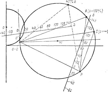
Fig. 16
Second method. As a pole the point of idling O 'gets out. The scale of sliding is inscribed in parallel to lines of moments between the line of useful power and perpendicular to the line of center in the point of idling. Crossing of segment (or its extension) of secondary current I '2 some loading point with a scale will define on a scale a sliding corresponding to this point.
After the plotting of sliding scale a circle of diagram is broken up on the row of points. By these points next values are determined: I 1, соs φ M and МE. In order to receive a moment on a shaft the moment of mechanical losses is subtracted from the electromagnetic moment МE.
М = МE – Мmech.
After determination of I 1, соs φ M and M the following dependences are built:
I 1 = f (s), соsφ M = φ (s), M = ψ (s).