2015-08-13
 485
485The principal sizes of asynchronous machine (diameter and length of armature) are determined by operation mode and value of external load. If an asynchronous machine is designed for operation in motor and generator modes with commensurable powers, then a calculation must be conducted for these two modes and the sizes of machine get out those which turned out most. If load in the motor mode there is the far less load of the generator mode, then its sizes are determined by the generator mode. Therefore at the choice of parameters all requirements are taken into account on providing of normal motor mode. If an asynchronous machine operates only in the generator mode, then its sizes are determined by the generator mode.
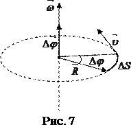
Fig. 4
The principle sizes of asynchronous machine can be defined by means of the known calculation equation:
D2li = (6,1∙104Pel) / αi∙ksh∙kw1∙A∙Bδ∙n (6)
Here Рel − electromagnetic power, V∙A. Electromagnetic power is determined:
а) for the motor mode
Рel = P 1 Eph 1 / Unom (7)
where Р 1 − power, consumed from a network; η – efficiency of motor; соs φ M − power-factor of motor; kE = Еph 1/ Unom − coefficient, taking into account a voltage drop across active and inductive resistances of motor; kE = 0,8÷0,9 − value, dependent on the number of pole pairs; large values behave to the two-poles motors; Р 2 − power at the output (on a shaft).
The rated value of primary current can be preliminary defined by a formula
I 1 nom = P 1 / (m 1 Unom)
b) for the generator mode
Рel = т 1 Еph 1 / I 1 = m 1 Unom I 1 nom kЕ; (8)
it is preliminary possible to accept kE = 1.
Unlike synchronous machines an armature current value for the asynchronous generators is not known, because it depends on the values of currents: through an excitative capacitor and magnitizing current. The exact value of stator current can be defined from the plotting of vector diagram of voltage at a test calculation. Preliminary the value of stator current can be defined by means of expression (for nominal power)
I 1n om = Inom cos φ / cos φG (9)
where Inom − current of load (nominal); соs φ – power factor of load; φ G − phase shift angle between voltage and armature current I 1.
For generators by power about 1 kV∙A
tg φG = 0,5÷ 0,7; cos φG = 0,86÷0,81.
The values of angles φ G depend on generator load in a strong degree. The less load current, the anymore angle φ G, and the armature current increases.
If in initial equation (6) to enter the relation λi = l i/ D, then
D = 3 √ (6,1∙104 Pel) / (α i ∙ kph∙kw 1 ∙A∙B δ ∙n∙λi) (10)
At the choice of the electromagnetic load A and B δ as it applies to asynchronous machines it is necessary to take into account the following.
1.Choice of large values B δ results in the increase of magnetizing current
Im = pF 2 / 0,9 m 1 kw 1 wph, (11)
Im ≡ B δ2 (12)
because F ∑ ≡ B δ; wph 1 ≡ 1/ B δ; F ∑ − total MMF of magnetic circuit.
2. With the increase of B δ the power-factor соs φ M goes down, dispersion diminishes, the short circuit current increases.
3. The value of excitant capacity increases with the increase of B δ, because the magnetizing current Im increases. General mass of the system increases.
4. Not only the numerical value of product A∙B δ, but also their correlation A / B δ have influence on the value of inductive resistances of short circuit Хsc and magnetizing Хm, and also on the value of magnetizing current Im.
Increase of ratio A / B δ increases a value Хsc, because
Xsc* = Xsc I 1 nom / Unom ≡ Λ А / В δ, (13)
where Xsc = Хs1+ Х’s2 − total inductive resistance of dispersion; Λ − coefficient, characterizing dispersion.
The less value of Xsc, the more torque, the more overload of motor. Therefore, if it is need, for example, to improve Мmax, it is necessary to increase B δ and to decrease A.
If to accept F ∑ =1,6∙ k δ1∙ k δ2∙ В δ∙δ∙ k μ and to take into account that (m 1∙ wph 1 / p) I 1 nom =Аτ, that
Im /I 1 nom = 1,78 ∙k μ(k δ1∙ k δ2) / (δ/τ)(В δ/ A)104 (14)
Xm = 0,56(kw 1 /kμ)(δ/τ’)(A/В δ)(Unom/I 1 nom )10-4 (15)
i.е. at increase of B δ and diminishing of A a relative value of Im /I 1 nom increases and, so, соs φ M diminishes.
For asynchronous machines at the choice of values A and B δ it is necessary to pay attention to the got values of magnetizing current Im, and so, соs φ M, and also on the coefficient of overload kovl, determined by Хsc.
At A∙B δ = const for the increase of power-factor соs φ M it is necessary to diminish a value B δ and to increase a value A, and for the increase of overload ability kovl it is necessary to increase a value B δ and to diminish a value A.
This contradiction is solved by the choice of such ratio between A and B δ, at which the most value of power-factor is provided at the given value of overload ability.
Recommended values of B δ and A for asynchronous machines, operating in the continuous duty, driven accordingly in the table. 1 and 2 (f = 400 Hz, m 1= 3, 2 p = 4).
Tabl. 1
| P 2, kW | 0,1 | 0,2 | 0,5 | 0,75 | 1,0 | 2,0 | 5,0 | |
| В δ, T | 0,36 | 0,48 | 0,55 | 0,57 | 0,6 | 0,62 | 0,64 | 0,66 |
Tabl. 2
| P 2, kW | 0,1 | 0,2 | 0,5 | 0,75 | 1,0 | 2,0 | 5,0 | |
| A, A/cm |
For asynchronous machines, operating in the individual systems of electrical equipment, it is rationally to choose frequency of rotation most. With the increase of frequency of rotation mass of machine diminishes. So, for example, mass of machine by power of 1 kW at n = 6000 r/m is approximately in two times more as compared to the same machine at n = 12 000 r/m. For individual turbine-generator sets at f = 400 Hz usually frequency of rotation is got out equal to 24 000 r/m (2 р = 2). At the choice of frequency of rotation it is necessary to check a machine for mechanical durability. For asynchronous machines a permissible linear speed equals to 80 m/s.
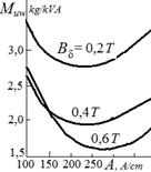
Data of tables. 1 and 2 for a choice of optimal electromagnetic load A and B δ are correct also for bipolar asynchronous machines with n = 24 000 r/m, what the curves of specific mass are evidence in a fig. 5.
 If the designed asynchronous machine in the traction mode operates on flyweight with the great moment of inertia, then in order to avoid its overheat during acceleration it is necessary considerably to reduce the linear load (up to 80÷100 A/cm at power about 1÷2 kW).
With the increase of rotation frequency and power of asynchronous machine an efficiency η and power factor Fig. 5 соs φ M are increased. Thus the less a power of machine, the stronger influence of rotation frequency on values of η and соs φ M, that is explained by the known correlations for specific losses and magnetizing current:
ΔP =P/Pel ≡ Mam/Pel ≡ (Pel/n)3/4/ Pel = 1/(Pel 1/4 n 3/4), (16)
im = Im/I 1 nom = l/l 2 = 4 √ (1/ Pel) = 1/ Pel 1/4 (17)
where Мam − mass of active materials.
Specific losses on unit of power (at B δ = const and jа = const) are proportional to 4-th root of power and 3-d root of frequency of rotation, i.e. with the increase of rotation frequency the specific losses fall and efficiency increases.
A magnetizing current is directly proportional to linear dimensions, and the load current is directly proportional to the second degree of linear dimensions.
So, relative value of magnetizing current im = Im/I 1 nom is inversely proportional to linear dimensions, i.е. a relative magnetizing current goes down with increasing power, that corresponds to growth of соs φ M for asynchronous machines. The increase of rotation frequency acts just the same, if to take into account that with the increase of n at f = const a ratio δ'/τ diminishes.
If operation of asynchronous machine is provided for traction mode, then it have to set oneself preliminary by values of efficiency and power-factor соs φ M. Recommended values η and соs φ M for three-phase asynchronous motors by frequency of f = 400 Hz and number of poles 2 p = 4 in the function of power driven to the table. 3.
Tabl. 3
| P 2 ,W | |||||||
| η | 0,40 | 0,53 | 0,63 | 0,70 | 0,76 | 0,77 | 0,78 |
| соs φM | 0,53 | 0,62 | 0,70 | 0,76 | 0,77 | 0,77 | 0,78 |
At р = 1 a value of η and соs φ M more than in a table. So, for example, at Р2 = 1000 W:η = 0,79, соs φM = 0,86.
For asynchronous machines attitude of length of machine toward the diameter λ = l/D ≈ λ i gets out greater, than for synchronous machines, i.е. asynchronous machines are executed relatively longer, than synchronous, at the same quantity of poles.
There is an area of optimal value of λ i which gives the least value of mass and fabrication cost at given energy rates. On the basis of theoretical researches and their practical confirmation for asynchronous machines next optimal values are set for λ i = f (р) at condition that surface speed and flywheel moment (GD 2) does not limit the choice of diameter value:
λ i = li / D = 1,6 p-2/3 (18)
λ’ i = li / τ = 3√ p (19)
The optimal value of λ i at given number of pole pairs depends also on the diameter (powers) of machine – is decreased at the increase of diameter. The optimum of ratio λ i diminishes with increasing of power. The choice of ratio λ i in defiance of geometric similarity is often determined by the terms of machine cooling.
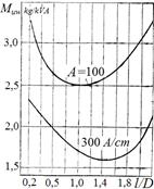
As it applies to the asynchronous generators of small power dependence of specific mass of attitude of armature length toward its diameter illustrated by curves, brought around to a fig. 6.
 As researches show, asynchronous generators must to have less values λ i, then asynchronous motors, for providing of the small nominal sliding.
By the chosen value λ i a calculation armature length is determined: li = λ i D (20)
Checking of this value is thus conducted under the required value of E.M.F. in generator mode: li = (Eph 1 I1nom ∙p∙m 1) / (ksh∙kw 1 ∙f∙ π2∙α i ∙ A∙B δ∙ D 2) (21)
Length of active part of armature in the first approaching it is possible to assume by an Fig. 6 equal to calculation.