2015-08-21
 379
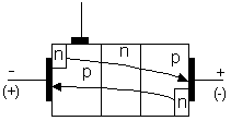
379The diode and the triode thyristors can conduct current only in one direction. It is impossible to use them to control AC current. In order to control AC current symmetrical thyristors are used (Fig.6.6). They are controlled semiconductor devices with two-way conduction. When the controlling pulse is applied to the circuit, such thyristor switches to ON condition independently of power supply polarity.
When the applied voltage has “- +” polarity the thyristor upper part is working. When the reverse voltage is applied the lower part of the thyristor is working.
a b
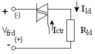
Fig.6.6. Symmetrical thyristor: a - structure, b - connection diagram
Let’s compare the operation of the symmetrical and common thyristors. Let’s apply AC voltage to the input of the common thyristor (Fig. 6.7a). The load voltage will look like on the graph (b). If we apply AC voltage to the symmetrical thyristor, we will get the load voltage looking like on the graph (c).
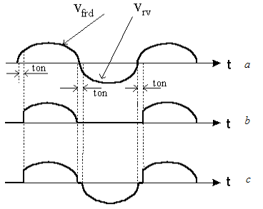
Fig.6.7. Oscilograms: a – of input values, b – of common thyristor load voltage, c – of symmetrical thyristor load voltage
6.4.Parameters of semiconductor thyristors
The main static parameters of a thyristor which can be found from its CVC are:
1. The turn-on current Ion. This is a current in the load circuit necessary to switch thyristor from OFF to ON condition.
2. The hold-on current Ihld. This is a current in the load circuit sufficient to keep ON condition of a thyristor (Ion> Ihld).
3. The voltage between an anode and a cathode when a thyristor is opened at the given load current Uopn.
4. The DC turn-on current of the controlling electrode at which a thyristor changes condition from OFF to ON.
5. The DC voltage of the controlling electrode, which corresponds to the turn-on current.
6. The “not turn on” voltage at the controlling electrode. This is max. value, which doesn’t provoke the thyristor switching.
7. The limiting DC current at ON condition.
8. The limiting DC voltage at OFF condition.
9. The limiting reverse DC voltage.
The dynamic parameters of a thyristor are:
1. Turn-on time. It is a period between the beginning of the control pulse and the moment when the value of the forward voltage is reduced up to 10% of its initial value.
2. Turn-off time. It is a limiting period between the moments when the forward current passes through zero and the repeatedly applied voltage, which doesn’t cause a thyristor turning on, passed through zero.
3. The critical current increasing speed at turn-on thyristor condition. It is the largest value of current increasing speed which doesn’t cause thyristor damage.
4. The critical voltage increasing speed at turn-off thyristor condition. It is the largest value of voltage increasing speed which doesn’t cause thyristor switching from off to on-condition.
The thyristor control circuit is characterized by minimum voltage and current that provide dependable turning on of the thyristor, and limitng voltage and current that don’t cause thyristor damage. Control pulses must be short and have a steep front. However, duration of a pulse must exceed the turn-on time of the thyristor. The limiting duration of a control pulse is within 15-20μsec.