2020-05-25
 124
124
For viscous petroleum products often use the Engler’s viscometer (Fig. 8.7.2).
The liquid flows in these viscometer through a calibrated hole. And then the ratio of the time of outflow of 200 ml of oil through a calibrated hole of the viscometer at a given temperature t to a time of outflow of 200 ml of distilled water at 20°C is determined. The Conditional viscosity at a temperature t is indicated by 0 CVt.
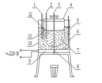
Fig. 8.7.2. Engler’s viscometer:
1,2 – thermometer; 3 – pin (valve); 4 – cover; 5 – water or oil tank (thermostat); 6 – mixer; 7 – tank with tested petroleum products; 8 – calibrated hole; 9 – heater
There is an empirical dependence between the values of conditional °CV and kinematic viscosity:
for ν from 1 to 120 mm2/s: νt = 7.31⸱ °CVt – 6.31/° CVt (8.7.3)
for ν > 120 mm2/s: νt= 7.34⸱ °CVt (8.7.4)
You can transfer viscosity from one system to another using a nomogram (Appendix 4).
For hydrocarbons, viscosity depends significantly on their chemical composition. It rises with increasing molecular weight and boiling point. The presence of lateral branching in the molecules of alkanes and naphthenic and an increase in the number of cycles also increase the viscosity. Viscosity increases in the row of alkanes-arenas-cyclones.
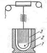
The viscosity of the most viscous petroleum products is determined on a rotary viscometer. These methods are based on measuring the force required to rotate the inner cylinder relative to the outer one when filling the space between them with the test liquid at a given temperature t (Fig. 8.7.3 a), or the speed of rotation of the rotor at a fixed force (Fig. 8.7.3 b).
In addition to standard methods for determining viscosity, non-standard methods are sometimes used, based on the measurement of viscosity by the time of falling of the calibration ball between the marks or by the time of attenuation of vibrations of the solid body in the test liquid (Fig. 8.7.4).
 | |||
 | |||
A b
Fig. 8.7.3. Rotary viscometers:
1 – stator; 2 – rotor; 3 – tested oil product.

Fig. 8.7.4. Measurement of viscosity by the time of falling of the calibration ball