2015-08-21
 259
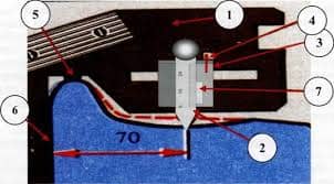
2591. Straight spur gear on the shaft -  ;
;
2. Helical spur gear and worm gear on the shaft -  ;
;
3. Bevel gear on the shaft -  ;
;
4. Coupling and gear located on a cantilever portion of the shaft -  ;
;
5. Pulleys or sprockets -  ;
;
6. Commercial seals - h 11;
7. Inner ring of a bearing - k 6;
8. Outer ring of a bearing - H 7;
9. The width of a keyseat in the shaft - P 9;
10.The width of a keyseat in the hole of a hub - JS 9.
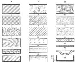
During treatment of the shaft besides errors of linear dimensions errors of geometrical shapes and errors of surfaces disposition arise.
Possible errors of geometrical shapes are non-cylindrical surfaces, non-rounding, non-flatting.
 For shaft portions and gear holes tolerances of cylindrical surface should be taken into account. Sign /○/ marks tolerance of cylindrical surface. The magnitude of this tolerance is determined as 0.3· t ·10-3, where t is diametrical tolerance range in micrometers (table 14.2).
Table 14.2