2015-04-17
 581
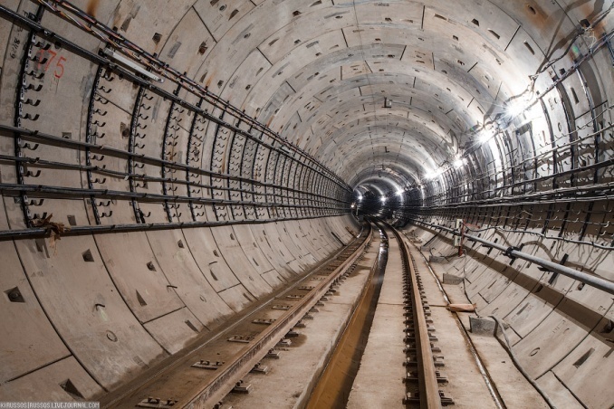
581The metro is one of the most efficient mode of public transport. It is a very complicated system including track ways between stations. The metro track differs from conventional railway track.
| 
|
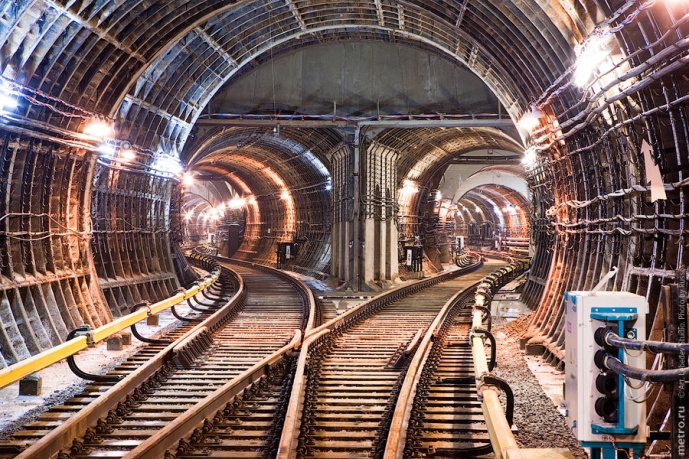
| a - General Arrangement of the Metro Interstation Tunnel (Общий вид перегонного тоннеля метрополитена) | b - Crossover Chambers with scissors crossings (Камеры съездов) |
Figure 22.1 General Arrangements of Metro Tunnels
The rails in the metro rest on concrete sleepers to keep the air free from dust. Were the track embedded in slag, gravel, sand, earth or even broken stone, called the ballast, the trains would be followed by dust clouds. The metro sleepers are shorter (0.9 m.) than those for the heavy rail track (2.7 m), and are separated by a drainage gutter (fig. 22.1a; 22.2). The contact rail, laid alongside the track throughout the line, carries a high voltage of 825 volts. It is attached to the brackets and transmits direct current to the train electromotor through the current collector (fig. 22.1; 22.2).
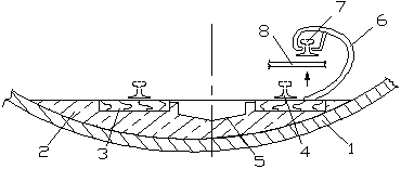
Figure 22.2 Layout of the Underground Track (схема пути метрополитена)
1 - Tunnel Lining (обделка); 2 – Concrete Base (бетонное основание);
3 – Semisleeper (полушпалок); 4 – Rail (рельс);
5 – Drainage Gutter (водоотводной лоток); 6 – Bracket (кронштейн);
7 – Contact Rail (контактный рельс);
8 - Train Current Collector – (токосъёмщик поезда)
The main part of any underground railway system is an interstation tunnel (fig. 22.1a). It may be a one-way tunnel with single track or a tunnel with double tracks. The New York Subway has four-track sections including a regular express service. The total length of the New York Subway is 337 km with 468 stations that are operated around the clock and used by 21 one-way lines and three shuttle services. Three-track sections are used for express service during rush hours.
The lining in the tunnels has a circular shape (fig.22.1). As a rule, it is made of reinforced concrete segments or cast iron liners in separate units. The trains divert from one track to another using crossovers (fig. 22.1b; 22.3).
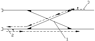
Figure 22.3 Diagram of Crossovers and Stub-end Tracks (схема съездов и тупиков)
1 – Crossover (съезд); 2 – Stub-end Track (тупик); 3 – Train-set (поезд)
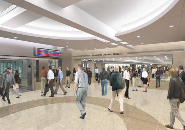
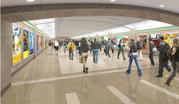
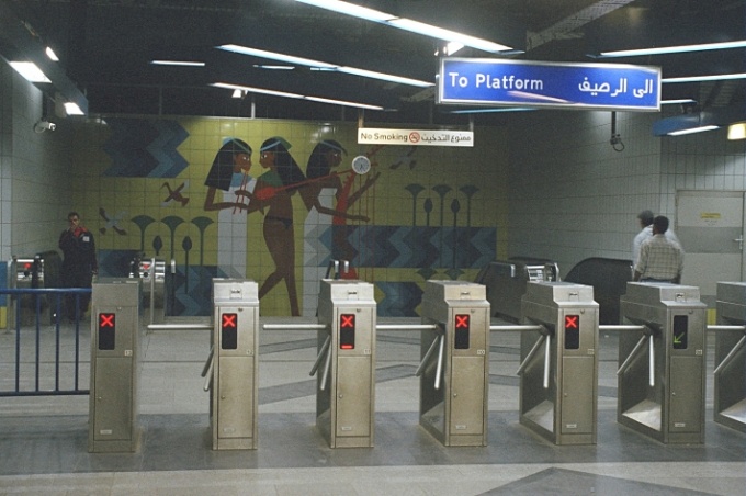
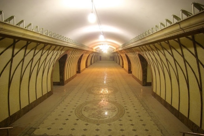
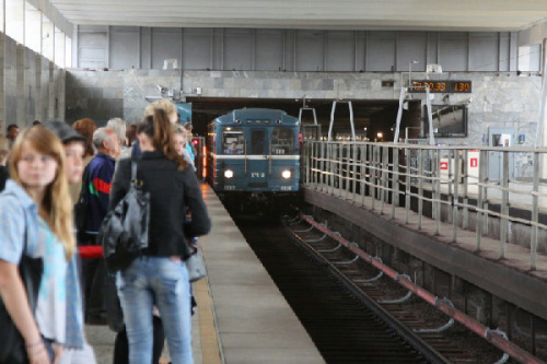
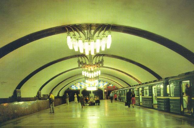
The metro carries yearly millions of passengers, and the stations are collection points for them. A metro station is usually a surface or an elevated railway station with ticket offices and automatic fare collection gates (AFC) or turnstiles (fig. 22.4c). The logo of each metro company marks the entrance of the station at street level. Station planning must provide a safe environment for passengers and meet the functional and aesthetic requirements. Attractively designed metro stations represent a continuation of the aboveground architecture. They are fully air-conditioned with required temperature and humidity though the stations are deep below street level. Usually passengers do not notice whether they are moving above or below ground because the structural layout itself creates the atmosphere of “a city within a city”, and the underpasses are densely packed with retail outlets.
| 
|
| a - entrance/exit | b – concourse (вестибюль) |
| 
|
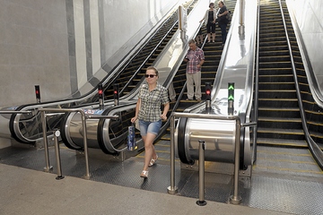
| c - entrance turnstile (входные турникеты) | d – three-band escalator |
Figure 22.4 A typical underground station
A typical underground station may have up to several ground level entrances and exits. They should allow for straight and short passageways that connect entrances to the fare paid zone, which is behind the line of turnstiles. Station access points must be equipped with one or more wide gate for wheelchair users and passengers with baby carriages. The width of the underpasses should range between 2 and 6 m, the height cannot be less than 2.5 m. The routes must be unobstructed and information including route maps is clearly visible throughout the station. The signs must display messages in English and in the native language.
Sanitary engineering, air ventilation chambers, lifts and ancillary rooms further facilitate the metro station. Disabled and passengers with heavy luggage and trolleys can use lifts.
The number as well as sizing of the platforms, escalators and subways, which are station elements, is dependent on the number of people using the station. To determine the optimum capacity of an underground station it is necessary to consider not only the number of passengers passing by continuously, but also the maximum number of passengers the station can deal with effectively. The regular number index of any station is measured by the number of passengers for a station and is equal to 20-30% of total train capacity. If stations are located near terminals, theatres, etc. the quantity index must be equal to 50%. The stations located next to large sports stadiums or concert arenas have the quantity index that is equal to 100% of overall train capacity because occasional events generate a powerful passenger flow over a relatively short period.
It has become common to provide escalators for upward and downward movement, and to allow passengers to change levels within the station. Escalators connect the underground platforms with concourses, staff offices and E&M plant rooms with electrical and mechanical equipment. An escalator system involves an inclined tunnel for three moving stairs, a power-driven station to move the stairs, fig. 22.5) and a tensioning station for a tensioning device.
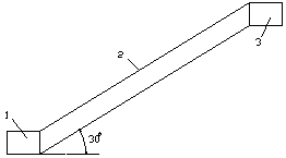
Figure 22.5 Escalator Facility (эскалаторный комплекс)
1 – Tensioning Station (натяжная камера); 2 – Escalator Tunnel (эскалаторный тоннель);
3 – Power-driven Station (приводная станция)
The diameter of the inclined tunnel is 8.1 m. Sometimes there are normal stairs between the two moving lanes, used in case the escalator breaks down. Stairs and escalator widths must be adequate for emergency evacuation. Today’s escalators provide ever increasing levels of reliability, comfort, roughened handrails and non-slip treads (fig.22.4d). The driving machinery uses the planetary gear arrangement with lower energy consumption because one direct drive machine powers both steps and handrails. The escalator safety enhances if the movement of step band and handrail is fully synchronized.
The performance of modern escalator systems is due to reliable technology and “intelligent” electronic monitoring and control. If malfunctions occur, automatic control units help to find them quickly. Stop switches provide safe access to all escalator machine spaces to enable the authorized personnel to keep the equipment in service. As escalators may go out of service, each metro system has its own program of ongoing maintenance and continuous monitoring.
Platforms are very important parts of the station as passengers gather, enter the trains and change routes (fig. 22.6 a,b; 22.7) there.
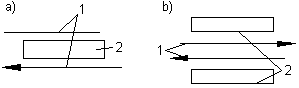
Figure 22.6 Diagram of the Underground Stations (схема станций метро)
1 – Track (путь); 2 – Platform (платформа)
Two factors regulate the overall configuration of stations. The first is the train length that determines a clear platform length. The second factor is the choice between side or island platforms (fig. 22.6; 22.7).
| 
|
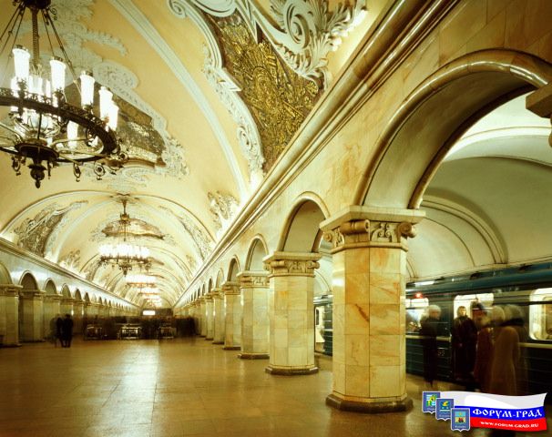
| a - Single Span Station (односводчатая станция) | b - Deep pillared-trispan Station |
| 
|
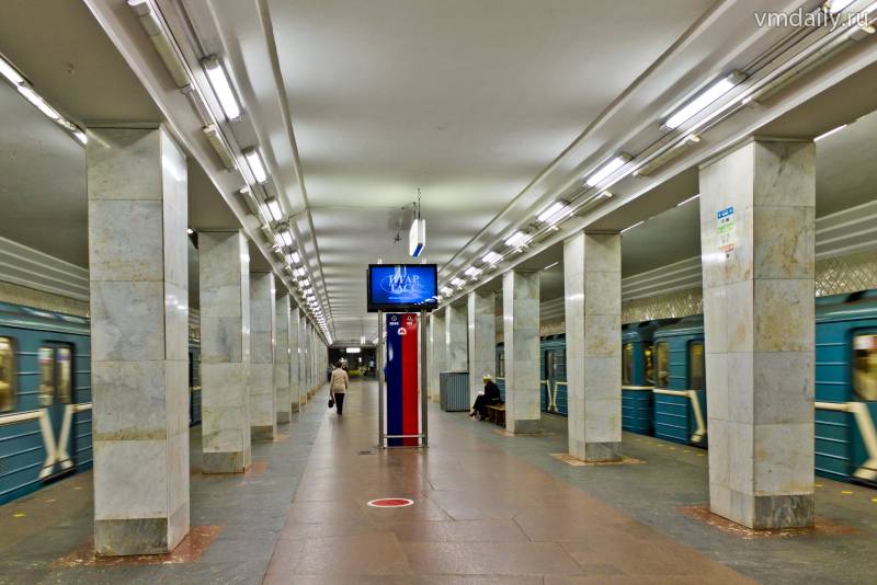
| c – Station with simple flat-slab ceiling | d- Station of side type |
| 
|
| e - Single Span Station of island type | d - Station of island type with simple flat-slab ceiling |
Figure 22.7 Types of Metro Stations
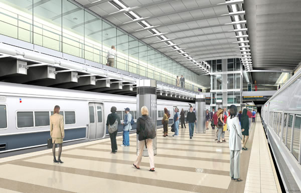
When double-bored tunnels are proposed, island platforms are preferred. A single row of columns in the centre of the platform or on both platform sides is a normal structural solution. A column-free platform also offers advantages, including an enhanced feeling of spaciousness. Architecture and interior design should satisfy passenger needs. Seating should provide passengers with comfortable waiting for trains but should not form any obstruction. Floor surfaces should be firm, easy to clean and made out of non-slip materials. Artificial lightning enhances the interior of the station. Platform edges must have strips of high contrasting colour (hazard tape) to warn passengers and prevent access to the tracks.
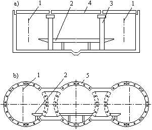
Figure 22.8 Diagram of Structures of the Underground Stations
(схема конструкций станций метрополитена)
a – Shallow-laid Station (станция мелкого заложения);
b – Deep-laid Station (станция глубокого заложения);
1 – Track (путь); 2 – Platform (платформа); 3 – Pillar (колонна, стойка);
4 – Ceiling Slab (плита перекрытия); 5 – Tunnel Lining (обделка)
Some platforms are equipped with automatic platform screen doors, which allow a full load of passengers on and off the cars within 90 seconds. These doors allow people to enter the cars only when the train stops in accurate alignment with the barrier doors. Platform screen doors differ from platform edge doors (PEDs). The former are total and full height barriers between the station floor and ceiling, the latter do not reach the ceiling. Besides these two, there are automatic platform gates called half-height platform screen doors. They are chest-height sliding doors at the edge of passenger platforms creating a safe waiting environment and preventing people from accidental falling or deliberate jumping off the platform waiting area onto tracks where they can be electrocuted or run over. Many stations on the Jubilee Line and the Canary Wharf Station in London, are equipped with glass protective barriers, and contain bright coloured banding to make them more visible.
Pillared-trispan structures are constructed for deep stations (fig. 22.7b). The central span is used for a passenger platform and the side spans are used for track ways. Span ceiling stations have pillars, which serve as the principle-bearing element. The result is a perfect harmony between attractiveness for the eye and technology. As a rule, the floors of shallow-laying stations are made of flat panels (fig. 22.7d). All station platforms, escalators, corridors and tunnels are under closed circuit television surveillance.