2015-08-21
 447
447Gear pump sucks the gas up from the subterranean gas storage and brings it into two fuel fillers.
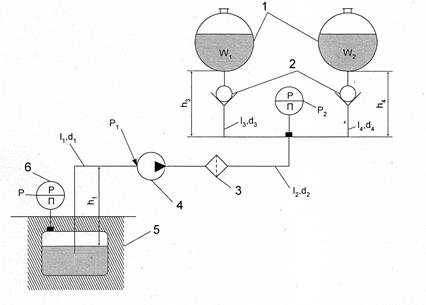
Fig.2. Schematic diagram of the fuel supply: 1 – fuel-filler; 2 – non-return valve; 3 – filter; 4 – gear pump; 5 – gas tank; 6 – manometer
Determine:
1.The absolute pressure P1 at the entrance of the pump, if the pump deliver is Q, pipeline length is l1, its diameter is d1, gage pressure in the gas storage is P = const.
2. Required head of the pump, if gage pressure in point A is equal to P2, length of the pipeline is l2, its diameter is d2.
3. Diameters of the pipelines d3 and d4, when minimal positional heights of the tanks are h3 and h4.
4. Time t of tanks filling.
Gas viscosity coefficient is ν, gas specific weight is γ, local resistances, set in the pipelines are shown in the schematic diagram. The height of liquid column in tanks is neglected. Atmospheric pressure is 760 mm of mercury head.
Solution technique:
1. Determine Re-number, λ, Σh, using the given data of Q, d, and l1. Pipeline length on a straight segment let be equal to h1.
2. Calculate the pressure at the entrance of the pump, using the data of h1, P and Σh.
3. Determine the flow velocity V of liquid, then Re-number, and the resistance coefficient λ, using assigned consumptions Q and assigned diameter of pipeline d2.
4. Calculate the head losses from the gear pump to the triple (point A). Assigned data of local resistance coefficients should be taken from table [1].
5. Using given data of P2, h2, and Σh, calculate the head H1 req.
6. Using given data of W1, W2, determine the fuel consumption in each tank.
7. Setting the data row of d3 and d4, calculate the gas flow velocity in the pipeline, Re-number, resistance coefficient λ.
8. Calculate the required head value H for each of d3 and build the dependence diagram H=f (d3).
9. Using the available head, determine d3 and d4 then choose the standard one.
10. Calculate time t, using the value of pump deliver and total volume.
Table 2
| Data | Variant | |||||||||
| Q,m3/s | 0,0036 | 0,001 | 0,0005 | 0,006 | 0,008 | 0,0012 | 0,0014 | 0,0016 | 0,0014 | 0,0018 |
| W1, m3 | 1,6 | 1,4 | 2,4 | 3,6 | 4,2 | 4,0 | 4,6 | |||
| W2, m3 | 0,5 | 0,8 | 0,7 | 1,2 | 1,5 | 1,8 | 2,1 | 2,3 | ||
| γ, N/m3 | ||||||||||
| P2, kPa | ||||||||||
| P, kPa | ||||||||||
| h1, m | 1,5 | 2,5 | 3,5 | 4,5 | ||||||
| l1, m | 1,2 | 1,8 | 2,4 | 3,5 | 4,5 | 5,5 | 6,5 | |||
| l2, m | 6,5 | 4,5 | ||||||||
| l3, m | 2,2 | 2,4 | 2,6 | 2,8 | 3,5 | 4,5 | ||||
| l4,m | 2,4 | 2,6 | 3,0 | 3,2 | 3,4 | 3,5 | 4,4 | |||
| d1, m | 0,025 | 0,02 | 0,024 | 0,018 | 0,026 | 0,03 | 0,032 | 0,022 | 0,02 | 0,036 |
| d2, m | 0,012 | 0,014 | 0,016 | 0,018 | 0,014 | 0,016 | 0,018 | 0,02 | 0,022 | 0,024 |
| v* 10-6 ,m2/s | ||||||||||
| h3, m | 1,5 | 2,2 | 2,2 | 3,0 | 3,4 | 2,0 | 2,5 | |||
| h4,m | 1,2 | 2,2 | 2,4 | 3,0 | 3,2 | 2,5 |