2015-08-21
 367
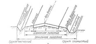
367 Fig.4. Schematic diagram of the fuel system: 1 – reserve tank; 2 – transfer pump; 3 – throttle; 4 – filter; 5 – non-return valve; 6 – service tanks
Aircraft fuel system (Fig.4.) transfer pump of delivery Q supplies T-1 kerosene at the temperature 20 0C to service tanks 6. The service tanks filling should be finished simultaneously.
The liquid head in the tanks should be omitted. Flight altitude H and other data are given in the table.
Determine:
1. Sucking pipeline diameter d1.
2. Drive pump required power Np.
3. Diameters d3 and d4 of the pipelines connected to the service tanks.
Solution technique:
1. Determine the main sucking line diameter using H, Q, Pen, h1 and l1 data(let l1= h1+0.6 m) and the standard one.
2. Find the drive pump required power according to Pp, ηusf, and Q data.
3. Determine pressure at point M, using Q, l2, d2, Pp data; then determine fuel feeding value to the service tanks, taking into account data of W1, W2, Q.
4. Calculate the required pressure head value for each diameter, using a number of pipeline diameters and plot the Hreq= f (d) curve.
5. Determine the d3 and d4 pipeline diameters using available pressure head value, and choose the standard ones.
Note: Atmospheric pressure versus flight altitude curve is given in the Appendix.
Table 4
| Data | Variant | |||||||||
| H, km | ||||||||||
| Pen, kPa | ||||||||||
| Q,m3 /s | 0,0010 | 0,0012 | 0,0014 | 0,0016 | 0,0018 | 0,0020 | 0,0022 | 0,0024 | 0,0026 | 0,0028 |
| ηusf | 0,97 | 0,96 | 0,95 | 0,94 | 0,93 | 0,92 | 0,91 | 0,9 | 0,89 | 0,88 |
| W1, m3 | ||||||||||
| h1, m | 2,5 | 2,3 | 2,1 | 1,9 | 1,7 | 1,5 | 1,3 | 1,1 | 0,9 | 0,7 |
| d2, m | 0,014 | 0,016 | 0,018 | 0,02 | 0,022 | 0,024 | 0,026 | 0,08 | 0,03 | 0,033 |
| l2, m | ||||||||||
| h3, m | 0,2 | 0,4 | 0,6 | 0,8 | 1,0 | 1,2 | 1,4 | 1,6 | 1,8 | |
| l3, m | ||||||||||
| h4, m | 0,2 | 0,3 | 0,4 | 0,5 | 0,6 | 0,7 | 0,8 | 0,9 | 1,0 | 1,1 |
| l4, m | 1,1 | 1,3 | 1,5 | 1,7 | 1,9 | 2,1 | 2,3 | 2,5 | 2,7 | 2,9 |
| Pp, kPa | ||||||||||
| W2,m3 |